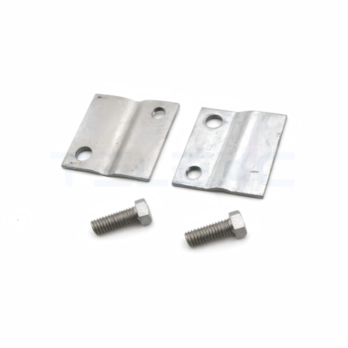
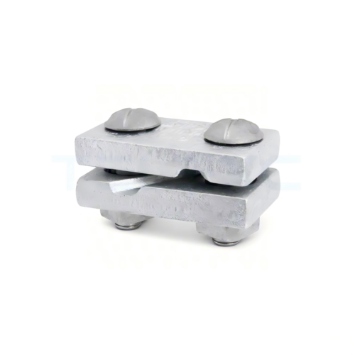
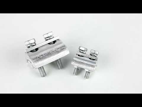
Crossover clamps are mechanical and electrical fittings used to connect conductors where two lines cross, intersect, or change alignment. It is installed in transmission and distribution networks to maintain conductor stability, electrical continuity, and safe spacing between cables. Crossover clamps are from high-quality materials such as hot-dip galvanized steel, aluminum alloys, copper alloy components, and stainless steel hardware. The material selection for the clamps depends on voltage level, conductor type, weather exposure, and environmental conditions. The crossover clamp consists of the clamp body, keeper plate, bolts and nuts, and grooved conductor seat. Using crossover clamps in overhead power infrastructure helps improve network reliability, conductor stability, electrical efficiency, and mechanical safety. Conducting quality assurance for the clamps is important because it ensures they can perform reliably in overhead power line systems under mechanical, electrical, and environmental stress. Quality assurance helps prevent conductor instability, overheating, electrical faults, and infrastructure failure.
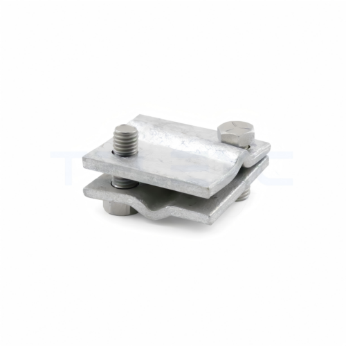
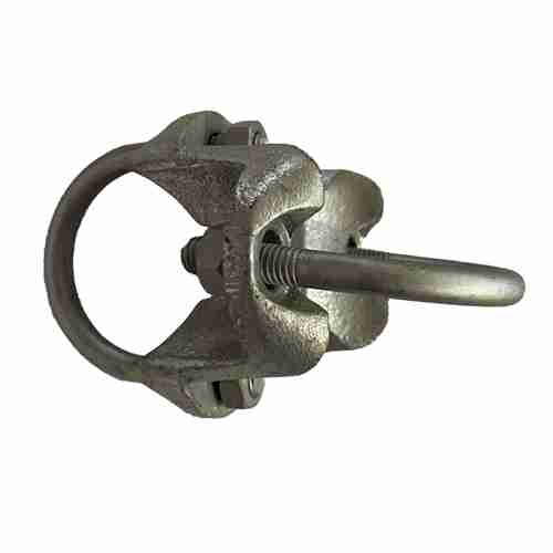
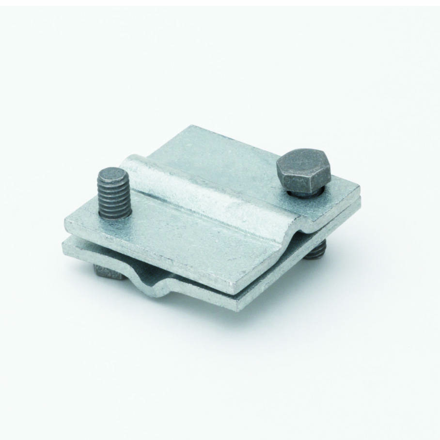
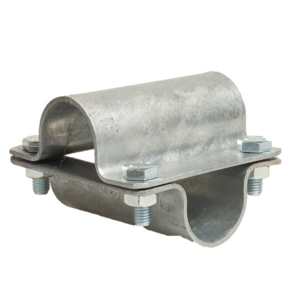
Crossover Clamp with Two Bolts – 1/4″ to 1/2″ Strand for 90° Crossing
Key Features
- Multiple Strand Sizes – Available for 1/4″, 3/8″, and 1/2″ strands.
- 90° Secure Crossing – Designed for perpendicular strand connections.
- Corrosion Protection – Galvanized coating ensures long service life.
- Heavy-Duty Bolting – Strong hex bolts provide a firm grip.
- Reduced Cable Wear – Minimizes abrasion at crossing points.

Types of crossover clamps used in overhead power infrastructure
Crossover clamps secure, support, and electrically connect conductors at crossing points. The type used depends on voltage level, conductor arrangement, mechanical load, and environmental conditions. Selecting the right crossover clamps helps achieve stable conductor support, reliable electrical contact, reduced maintenance requirements, and improved transmission system safety and efficiency.
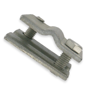
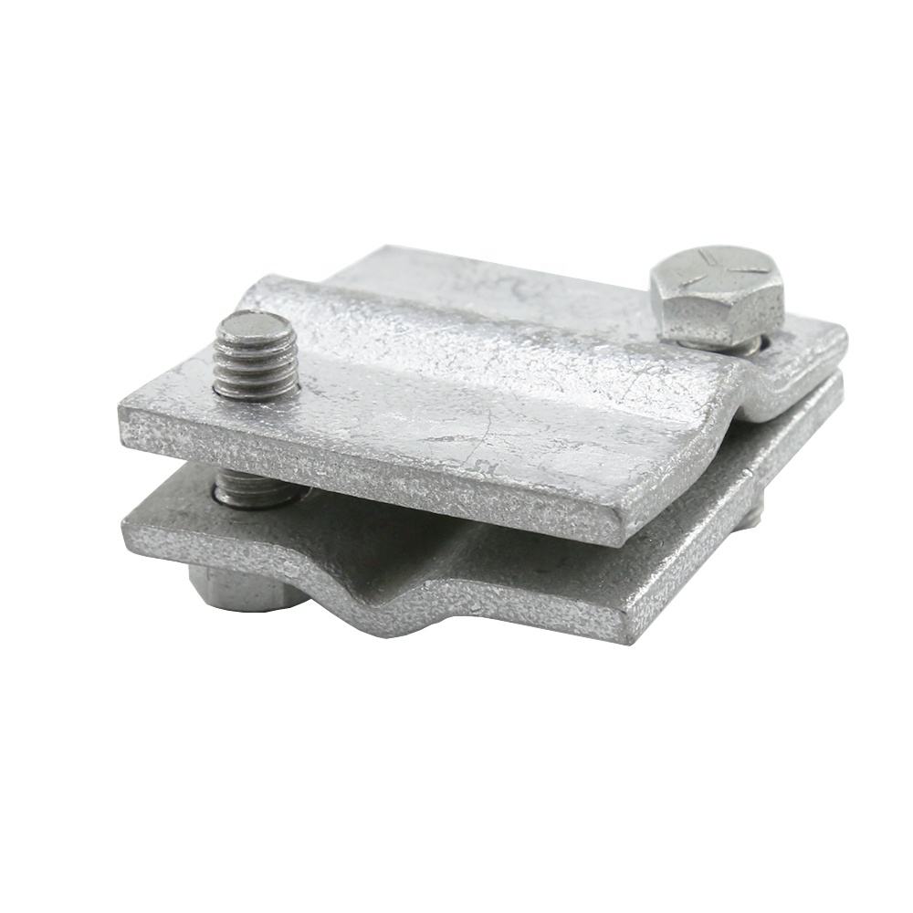
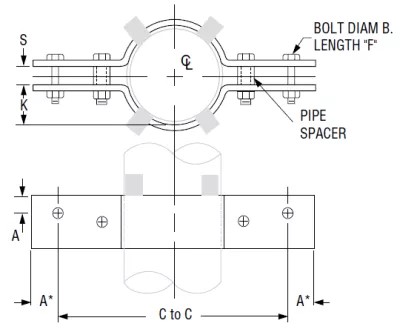
Parallel groove crossover clamp
This is the most common type of clamp used in distribution and transmission systems. It contains parallel grooves for holding conductors side by side, uses bolted compression for tightening, and is usually made of aluminum alloy or copper alloy. Parallel groove clamps serve in conductor crossing connections, distribution line branching, and permanent conductor joints.
Compression crossover clamp
These clamps use hydraulic compression to create a strong electrical and mechanical connection. It is installed using compression tools and provides high contact pressure. Compression clamps serve in heavy-load conductor crossings, high-current transmission systems, and long-span power infrastructure.
Suspension-type clamp
These clamps support conductors while allowing controlled movement caused by wind or thermal expansion. It mounts with suspension hardware and allows conductor flexibility. Suspension-type clamps include cushioning components in some designs. These clamps reduce conductor stress, reduce abrasion damage, and improves line stability.
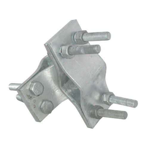
Bolted crossover clamp
This clamp uses nuts and bolts to secure crossing conductors. It offers simple mechanical design, adjustable tightening systems, and easy field maintenance. It serves in medium-voltage distribution lines and rural electrification projects.
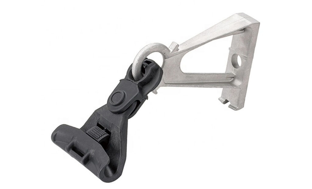
Insulated crossover clamps
Insulated clamps include protective insulation materials to improve electrical safety. These include polymer or rubber insulation covering. These materials reduce the risks of accidental contact and enhance environmental protection. The clamps serve in compact distribution systems, urban overhead networks, and areas with limited conductor clearance.
Dead-end crossover clamp
This is designed for terminating or anchoring conductors at crossing points. It consists of high-tension holding capability, a reinforced clamp structure, and is often used with anchor hardware. The clamp serves in angle towers, line termination points, and high-tension conductor crossings.
Armor rod clamps
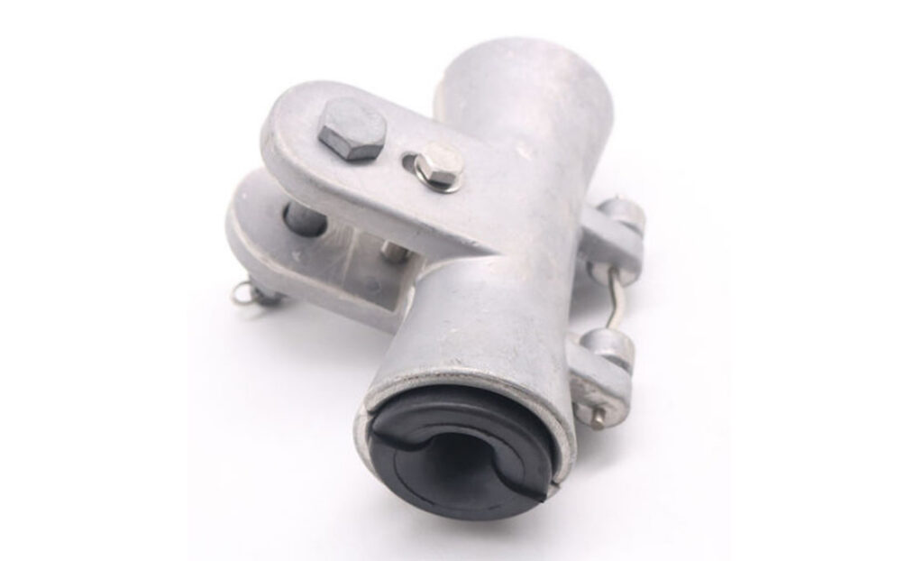
This combines armor rods with clamp systems to protect conductors from wear and vibration. It includes preformed armor rods to distribute mechanical pressure evenly. It serves in high-vibration transmission lines and long-span crossings.
Material selection for crossover clamps used in overhead power infrastructure
The performance and durability of crossover clamps depend on the materials used during manufacturing. It is important to consider the environments the clamps will serve in; for instance, they may face mechanical stress, heat, moisture, and corrosion. The material selected should ensure reliability and long service life in these conditions. Hence, it is crucial to check electrical, mechanical, and environmental requirements of the overhead power system. Poor material selection can lead to overheating, corrosion, conductor damage, clamp failure, and power outages in overhead networks. Common materials for crossover clamps include:
- Aluminum alloy—this is the most common material for crossover clamps in transmission and distribution systems. It offers high electrical conductivity, good corrosion resistance, and excellent thermal performance. Aluminum clamps serve in aluminum conductor systems, medium and high-voltage overhead lines, and humid environments.
- Copper alloy—this offers excellent electrical conductivity, good thermal conductivity, and strong resistance to overheating. It serves in copper conductor networks, grounding and bonding systems, and high-current connections. Copper alloys offer stable electrical contact, low contact resistance, and reliable current transfer.
- Hot-dip galvanized steel—this is crucial for structural clamp components that need high mechanical strength. It offers high tensile strength, strong load-bearing capability, and zinc coating for corrosion protection. Galvanized steel clamps serve in heavy-duty crossover clamps, high-tension transmission lines, and industrial installations.
- Stainless steel—this is crucial for bolts, nuts, washers, and corrosion-sensitive components. Stainless steel offers excellent corrosion resistance, high mechanical strength, and good resistance to moisture and chemicals. Steel clamps serve in coastal power infrastructure, high-humidity regions, and pollution-prone environments.
- Bronze and brass—this offers moderate conductivity, good corrosion resistance, and strong wear resistance. It serves in specialized conductor fittings and corrosive environments. Bronze and brass clamps provide durable electrical contact and good resistance to oxidation.
Checking quality assurance for crossover clamps
Quality assurance for crossover clamps verifies that each clamp meets mechanical, electrical, and environmental performance requirements before installation and during production. It prevents failures such as conductor slippage, overheating, corrosion, or mechanical breakage in service. Effective quality assurance ensures stable mechanical support for conductors, reliable electrical conductivity, and resistance to corrosion and environmental degradation. Here is how to check for quality assurance for crossover clamps.
- Incoming material inspection – this ensures only compliant and traceable materials enter production and reduces risk of failure. It includes checking material certification, chemical composition, mechanical properties, and coating quality.
- Dimensional and design verification—this includes checking groove diameter and conductor fit accuracy, bolt hole alignment and spacing, and compatibility with specified conductor sizes. It ensures proper mechanical fit and prevents conductor damage or slippage.
- Mechanical strength testing—crossover clamps face constant tension and vibration in overhead power networks. It undergoes tensile load tests, slip resistance tests, vibration fatigue tests, and torque tests. When selecting the clamp, it is crucial to ensure no deformation under rated load, no conductor slippage, and no cracking or structural failure.
- Electrical performance testing—key tests include contact resistance test, current carrying capacity test, temperature rise test, and voltage drop measurement. Quality assurance is important as poor electrical contact leads to overheating, energy losses, and fire risks.
- Corrosion resistance testing—the testing methods include salt spray tests, humidity chamber exposure, UV and weather aging tests, and coating thickness measurement.
- Coating inspection—surface quality affects the performance and lifespan of the crossover clamp. The QA process checks zinc coating uniformity, surface cracks, pits, burr-free finishing on grooves, and protective coating adhesion strength.
- Bolt and fastener quality checks—this includes thread accuracy and alignment, torque retention capability, anti-loosening performance, and material grade verification.
Common quality failures in crossover clamps
Quality failures in crossover clamps arise from deficiencies in material selection, manufacturing control, surface treatment, or assembly. These failures affect mechanical stability, electrical performance, and reliability of overhead power lines. These failures include:
- Material defects—the most common failure is poor-quality or non-compliant raw material. It includes incorrect alloy composition, presence of impurities, and low tensile strength compared to specification. Material defects cause premature clamp fracture, reduced service life, and increased risk of line collapse.
- Poor galvanization—common defects include uneven zinc coating thickness, flaking of the protective layer, incomplete coverage of clamp surfaces, and porosity in the coating layer. This leads to increased corrosion, weakening of structural integrity, and increased maintenance frequency.
- Dimensional inaccuracies—this includes incorrect groove size for conductor fit, misaligned bolt holes, and uneven clamp body. This leads to poor conductor seating, slippage under mechanical load, and increased conductor wear and abrasion.
- Insufficient mechanical strength—these failures include bolt loosening under vibration, clamp deformation, cracking at stress concentration points, and poor fatigue resistance. These failures lead to conductor instability, mechanical failure, and line outages.
- Electrical contact failures—these issues include high contact resistance due to poor surface finish, oxidation between contact surfaces, and loose conductor grip. These issues lead to localized overheating, power loss, and risk of fire in severe cases.
- Fastener and bolt failures – these include low-grade bolts that shear under tension, thread stripping during installation, lack of anti-loosening features, and corrosion of nuts and bolts. They lead to progressive loosening of the clamp, sudden mechanical failure and increased maintenance interventions.
Best practices for selecting the right crossover clamp
Selecting the right crossover clamps affects the conductor’s stability, electrical efficiency, and reliability of overhead power networks. To make the right decision, it is crucial to match the clamp type to system design, ensure conductor compatibility, focus on mechanical load requirements, select materials based on environment, and verify electrical performance requirements. Additionally, it is important to ensure compliance with IEC standards for overhead line fittings, ASTM material specifications, and utility grid codes. It is also crucial to check zinc coating thickness, uniformity of coating, and sealing of cut edges and bolt holes. Clamp selection guided by engineering specifications, verified standard compliance, and environmental risk assessment offers the most reliable systems.