
The PLC fiber splitter is a compact and reliable optical power distribution solution developed for modern FTTH, FTTX, and passive optical networks. It consists of advanced planar light wave circuit technology that ensures uniform signal splitting, low insertion loss, and long-term stability. The fiber splitter distributes optical signals from a central office to multiple endpoints. It does this while maintaining consistent optical performance across all output ports. It is a passive optical device with many input and output terminals such as EPON, GPON, BPON, and FTTX to connect to the main distribution frame (MDF) and the terminal equipment. PLC fiber splitters provide low-cost light distribution solutions with high stability and reliability. They function in data center networks to distribute fast data to servers and storage devices. They also serve in optical access networks to provide high-speed internet connectivity.
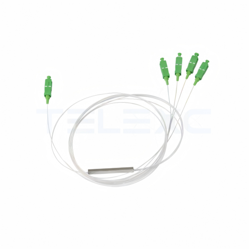
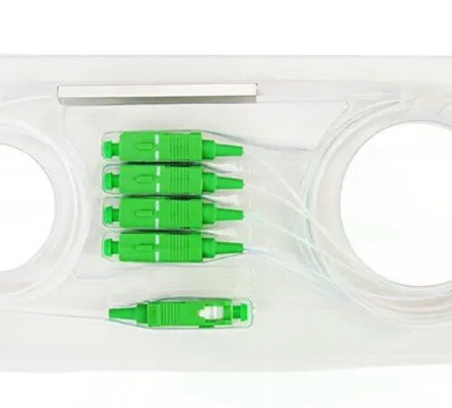
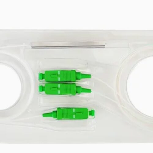
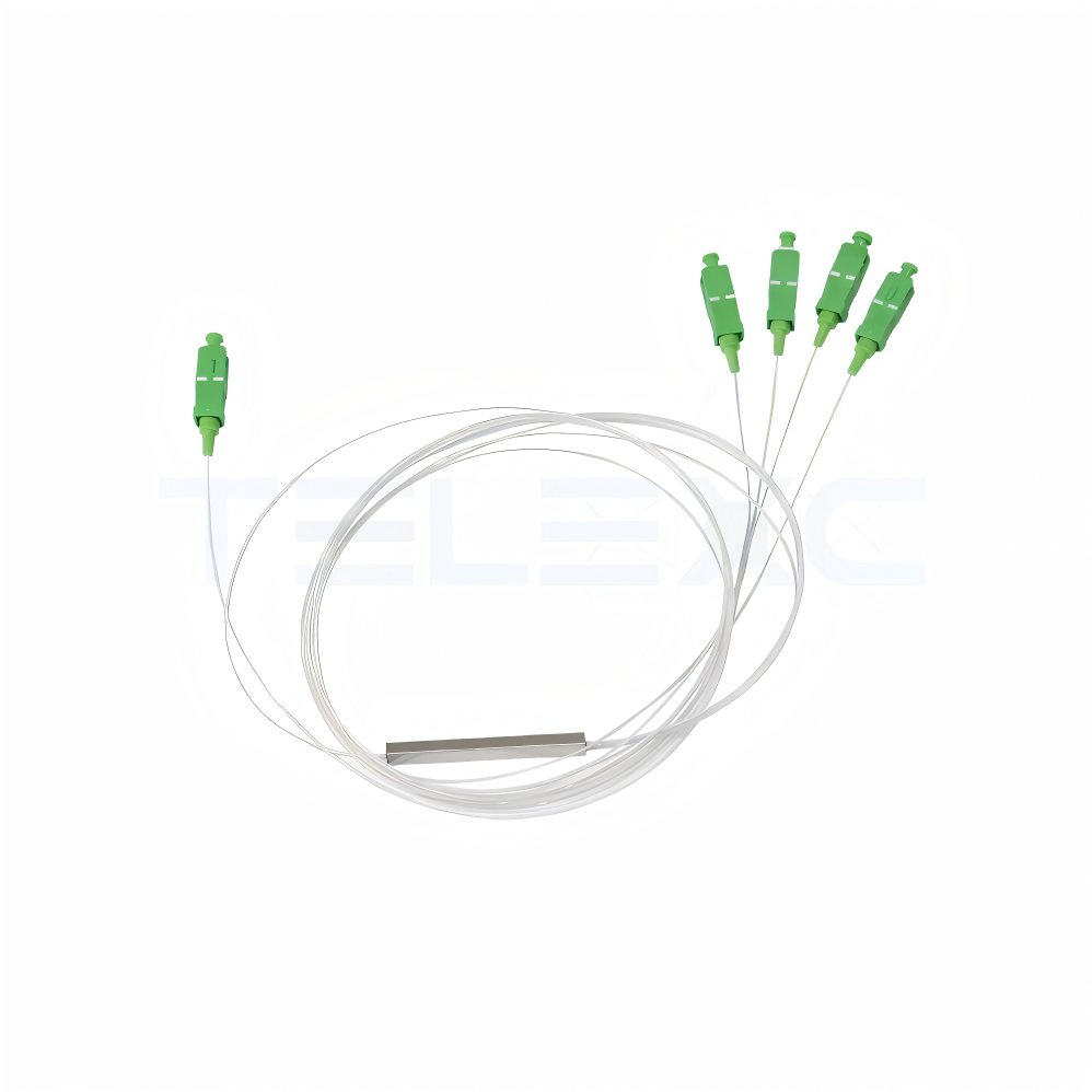
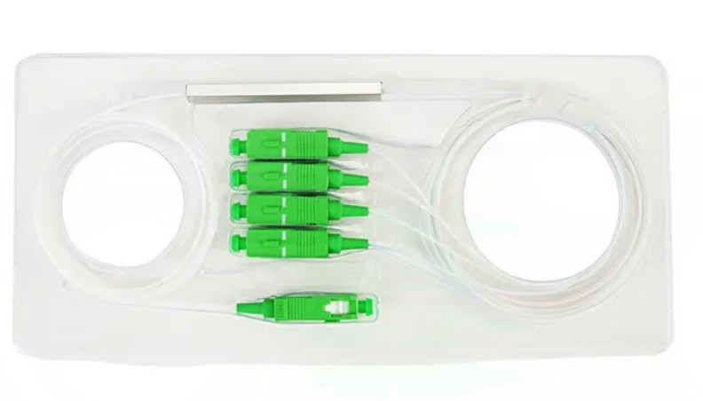
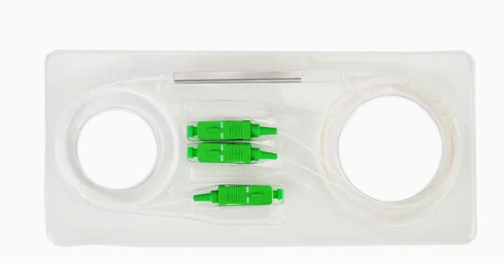
1×4 SC/APC Micro PLC Fiber Splitter – Telexc
Key Features
-
Compact micro design for space-saving installations
-
Uniform optical power splitting
-
Low insertion loss and low PDL
-
High return loss and excellent directivity
-
Wide operating wavelength range (1260–1650 nm)
-
Stable performance under extreme temperatures
- Operating Temp (°C)-40 to +85

Configuration and components of the PLC fiber splitter
The PLC fiber splitter is designed to distribute optical signals from one or more input fibers to many fibers. It has internal components designed to ensure low insertion loss, stable performance, and reliability in fiber optic communication networks. Its configuration depends on network requirements and includes a 1xN configuration with one fiber input and many output fibers; a 2xN with two input fibers and many output fibers; and packaging configurations to suit different installation environments. Here are its common components:
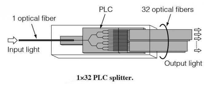
- Input fiber – the input fiber carries the optical signal from the optical line terminal or other transmission equipment into the splitter. It consists of a single-mode fiber, low attenuation, and high optical transmission efficiency.
- Optical fiber pigtails—the pigtails connect the PLC chip to external network components. It includes factory-terminated connectors, low insertion loss, and high return loss.
- PLC chip – this is the core component of the splitter, which divides optical power uniformly, maintains signal consistency, and supports wide wavelength operation.
- Waveguide circuit – the integrated waveguide network guides optical signals through the chip, controls signal splitting ratios, and reduces optical losses. This enables highly accurate and consistent power distribution.
- Fiber array block (FAB) – this aligns input and output fibers with the PLC chip. It ensures precise optical coupling, reduces signal loss, and maintains mechanical stability.
- Protective housing – this protects the internal optical components from environmental and mechanical damage. It protects the fibers from moisture, dust, vibration, and temperature fluctuations. It consists of ABS plastic, aluminum alloy, and stainless steel.
- Output fibers – these fibers transmit the divided optical signals to many network nodes. The fibers offer equal signal distribution, low attenuation, and consistent optical performance.
Classification of PLC fiber splitters
PLC fiber splitters classify into several criteria to help designers select the most suitable splitter for FFTH, GPON, EPON, and data center and telecommunications applications. These include:
By splitting configuration
This depends on the number of input and output ports. This may include 1xN splitters that serve in FTTH networks, GPON systems, and broadband access networks. 1xN splitters serve in redundant network architectures, signal monitoring systems, and telecommunications networks.
By packaging type
These include bare fiber PLC splitters, mini module PLC splitters, ABS box splitters, tray-type splitters, LGX cassette splitters, and rack-mounted PLC splitters. These splitters are economical, improve durability, have excellent protection, and organize fiber routing.
By connector type
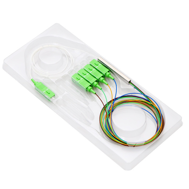
These include SC/APC splitters with angled physical contact ferrules and low back reflection. The SC/UPC splitter has ultra-physical contact polishing and low insertion loss. The LV PLC splitter has a compact connector design and high-density installations. The FC splitter has a threaded coupling mechanism and secure connection, and the ST splitter has a bayonet-style locking and legacy fiber networks.
By mounting method
These include wall-mounted PLC splitters for building distribution points and indoor FTTH networks. Cabinet-mounted splitter on outdoor fiber distribution systems and rack-mounted splitter for central offices and date centers.
By fiber type
These include single-mode splitters for long-distance transmission and low attenuation and multi-fiber splitters for high-capacity network deployments.
PLC fiber splitter installation guide
The installation of the PLC splitter is crucial for the deployment of fiber-to-the-home (FTTH), GPON, EPON, and other optical networks. Proper installation ensures low insertion loss, reliable signal distribution, and network performance. During installation, it is crucial to avoid contaminated connector end faces, poor cable management, incorrect port assignments, and failure to perform optical testing. The process include:
- Verifying splitter ratio and connector type before installation
- Cleaning all connectors using approved fiber cleaning tools
- Routing fibers to avoid excessive bending
- Securing the splitter inside the distribution box or cabinet
- And testing optical power levels after installation
The working principle of the PLC fiber splitter
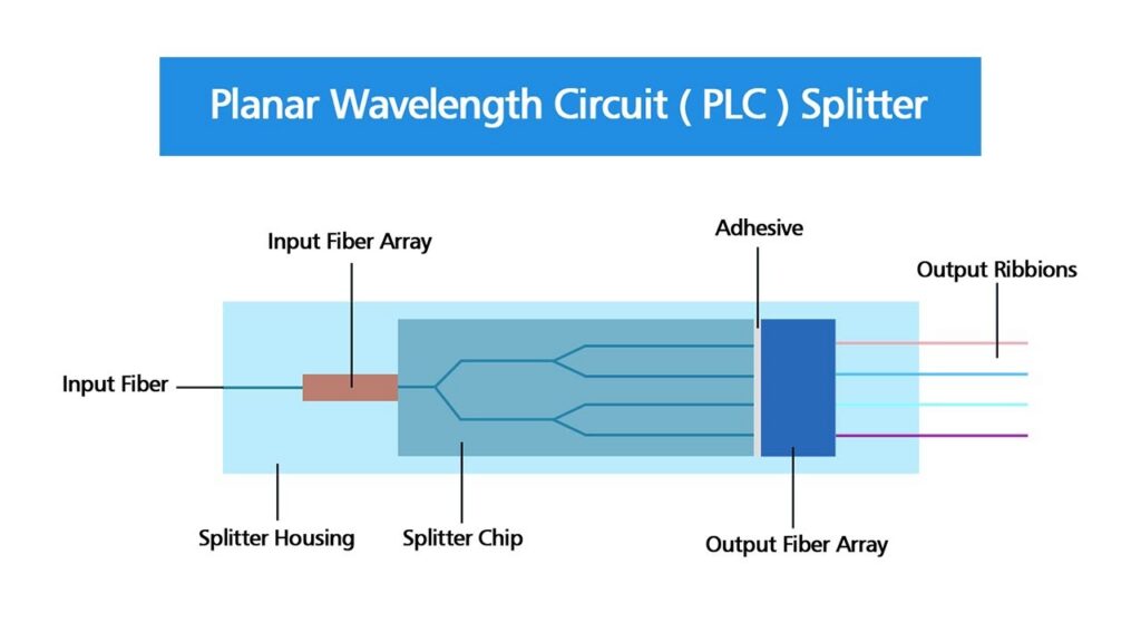
A PLC fiber splitter is a passive optical component used to divide a single optical signal into different outputs in fiber optic communication networks. Its operation depends on integrated waveguide technology rather than electrical or mechanical switching. When light enters the input fiber, it is guided into a silica-based PLC chip. The chip contains microscopic waveguide circuits, and the waveguides split the light across many paths. Each output fiber receives a proportional share of the original signal. The optical signal then follows a structured path to optical network terminals. The PLC splitters’ planar waveguide design enables high-density splitting, stable optical performance, low signal variation, and scalable network design.
Technical specifications for PLC fiber splitters
A PLC fiber splitter is defined by optical, mechanical, and environmental specifications that determine its performance in FTTH, GPON, EPON, and other optical networks. These vary by manufacturer and split ratio. The specifications ensure the splitter can deliver stable, uniform optical signal distribution across FTTH and GPON networks under diverse deployment conditions. These include:
| Category | Parameters | Specification | Notes |
| Optical performance | Operating wavelength | 1260-16500 nm | Supports GPON, EPON, CATV bands |
| Split ratio | 1×2 to 1×128/ 2xN | Higher ratios increase loss | |
| Insertion loss | 3.5-21.5 dB | Depends on split ratio | |
| Uniformity | ≥1.0-1.5 dB | Output port balance | |
| Return loss | ≥55 dB (APC) | Measures signal reflection | |
| Polarization dependent loss (PDL) | ≥0.3-0.5 dB | Signal stability factor | |
| Directivity | ≥55 dB | Isolation between ports | |
| Fiber characteristics | Fiber type | G.652D/G.657A1/A2 | Single-mode fiber standard |
| Fiber length | 1m-1.5m | Custom lengths available | |
| Fiber diameter | 0.9mm/2.0mm/3.0mm | Depends on packaging | |
| Connector types | Connector options | SC/APC, SC/IPC, LC/APC, LC/UPC, FC | SC/APC most common in FTTH |
| Mechanical design | Packaging types | Bare fiber, ABS box, mini module, LGX cassette, rack-mounted | Application-dependent |
| Housing material | ABS plastic/aluminum | Protection against environment | |
| Environmental conditions | Operating temperature | -40°C to +85°C | Telecom-grade standard |
| Storage temperature | -40°C to +85°C | Non-operational storage | |
| Humidity | ≤95% RH (non-condensing) | Prevents moisture damage | |
| Vibration resistance | Telecom standard compliant | Suitable for field deployment | |
| Reliability | Service life | ≥ 25 years | Typical design lifespan |
| Standard compliance | ITU-T G.671, Telcordia GR-1209/1221, IEC 61300 | Industry reliability standards |
How to select the right PLC fiber splitter
It is crucial to select the right splitter to achieve optimal performance, scalability, and reliability in FTTH, GPON, EPON, CATV, and telecommunications networks. It is important to consider network architecture, split ratio requirements, optical performance, installation environment, and future expansion needs. The selection process should consider:
- Determine the required split ratio – this determines how many users or network endpoints can be served from a single optical fiber. Choose the smallest split ratio that meets current and anticipated subscriber requirements to reduce insertion loss.
- Check the optical power budget – every splitter introduces insertion loss that affects signal strength. It is crucial to consider OLT send power, fiber attenuation, connector losses, splice losses, and ONT receiver sensitivity.
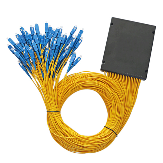
- Choose the appropriate packaging type—this may include a bare fiber splitter, mini module splitter, ABS box PLC splitter, and LGX cassette splitter.
- Select the right connector type – compatibility with the connector reduces installation complexity. SC/APC connectors offer low back-reflection characteristics.
- Verify fiber compatibility – the splitter should match the fiber type used in the network. For instance, G.657 fibers are ideal for FTTH installations involving tight cable routing.
- Access key optical performance parameters—it is crucial to consider insertion loss, return loss, uniformity, and polarization-dependent loss. Higher-quality splitters provide consistent output and better network stability.
- Check manufacturer quality and reliability—a good manufacturer provides consistent insertion loss performance, high-quality PLC chips, strict quality control, and technical support.
Applications of the PLC splitters
PLC fiber splitters have the ability to distribute a single optical signal to many endpoints with low loss and high uniformity. This makes them crucial in telecommunications, broadband access, data transmission, and smart infrastructure projects. They serve in:
- Fiber-to-the-home (FTTH) networks distribute optical signals from the central office to multiple subscribers. They help share bandwidth among users, reduce the need for dedicated fibers, and support large-scale broadband deployment.
- PON systems – the splitters are compatible with EPON and GPON systems. They allow multi-user signal distribution, passive network connectivity, and broadband access support.
- Telecommunications networks—they serve in LAN, WAN, and metro optical networks. The splitters offer traffic distribution, subscriber connectivity, and network expansion.
- CATV systems—the splitter supports optical video distribution in CATV systems. They distribute optical television signals and allow integration with broadband services. They offer consistent video quality, reduced infrastructure requirements, and signal delivery.
- Smart city infrastructure – smart city projects depend on extensive fiber optic networks for communication and monitoring. They serve in traffic management systems, surveillance systems, and environmental monitoring.