
Hybrid Fiber Optic Cable
Hybrid Fiber Optic Cable Guide
Overview of Hybrid Fiber Optic Cable Technology
A hybrid fiber optic cable is a physical composite cable. It combines optical fibers and insulated copper wires inside one outer jacket.
… Load moreShowing all 2 results
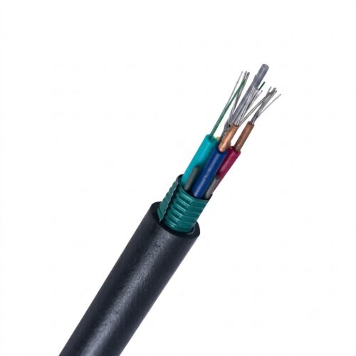
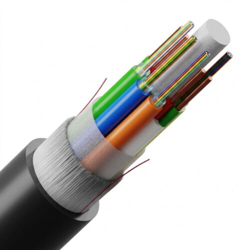
Glass strands carry high-speed light signals. Copper conductors deliver direct current power to active electronics.
Standard optical cables carry no electricity. Standard copper cables suffer heavy signal loss over long distances. Combining glass and copper inside one sheath solves both problems.
Field crews pull one cable instead of running two separate lines. This single-pull method slashes labor costs. It speeds up cable installation work in the field. It saves conduit space in cable trays and underground ducts.
Engineers deploy hybrid lines to power remote hardware where local utility power is missing. Central power supplies feed all connected devices. Technicians mount power converters at line terminals to match device voltage requirements.
Designers created composite cables in 1978 for undersea links. Operators adopted hybrid lines in the 1990s during network expansions. Today, networks use hybrid cables for 5G wireless sites, small cell nodes, campus backbones, and Wi‑Fi 7 access points. These access points need 40 Gbps throughput. Understanding cable structures, power limits, and field practices helps engineers build reliable broadband networks.
Structural Design and Technical
The inner structure of a hybrid cable balances physical protection, electrical insulation, and light transmission. Every layer has a specific function.

- Optical Fiber Sub-Unit: Encloses single-mode OS2 or multimode OM3 or OM4 fibers inside buffer tubes. Color-coded acrylate coatings follow TIA-598 standards for fast fiber identification. Single-mode glass keeps signal loss below 0.35 dB/km at 1310 nm wavelengths.
- Copper Power Conductors: Features insulated stranded copper wires sized 12 AWG to 20 AWG. Color-coded red and black insulation prevents wiring errors in dark field enclosures. Conductors carry low-voltage Class 2 power or Class 3 DC electrical power to remote active devices.
- Central Strength Member: Uses a non-metallic fiberglass rod or galvanized steel wire. Absorbs pulling tension during installation to protect inner glass elements from mechanical stress.
- Water-Blocking Barrier: Uses dry water-swellable tape or gel compounds around the cable core. Super-absorbent polymers swell on contact with water to seal voids along underground duct runs.
- Armor Shielding Layer: Features flexible aluminum interlocking armor or corrugated steel tape armor. Protects against crushing loads, soil pressure, and rodent damage in open trenches.
- Outer Protective Sheath: Uses Polyethylene for outdoor ducts, Polyvinyl Chloride for risers, or Low Smoke Zero Halogen compounds for plenum air spaces.
Power delivery depends on wire size, circuit length, and DC voltage levels. Standard PoE over Cat6A copper cables stops at 100 meters under IEEE 802.3bt rules. This creates severe PoE distance limitations for remote devices.
Hybrid optical lines bypass this distance limit. Using 12 AWG copper wires, hybrid cables deliver Class 3 power at 57 VDC across 600 meters.
Heavy-duty composite cables ensure power transmission up to 200 watts across runs up to 1,000 meters. Optical fibers suffer zero signal interference from adjacent copper wires, supporting data rates up to 100 Gbps per strand.
Main Type of Hybrid Cable Constructions
Engineers select hybrid cable constructions based on environmental hazards, mechanical risks, and installation pathways. Indoor sheaths use flame-retardant polymers, while outdoor jackets contain carbon black to resist solar radiation.
- Indoor Hybrid Cable: Features flame-retardant Low Smoke Zero Halogen jackets and tight-buffered fibers. Installed in interior cable trays, vertical riser shafts, and plenum air spaces.
- Outdoor Duct Hybrid Cable: Features heavy-duty Polyethylene outer jackets with water-blocking gel or swellable tapes. Installed in underground conduits subject to moisture and temperature shifts.
- Direct Burial Armored Cable: Reinforced with corrugated steel tape armor or thick aluminum interlocking armor. Placed in open trenches without a conduit to withstand soil pressure and rodents.
- Aerial Self-Supporting Cable: Integrates an external steel messenger wire or aramid strength yarns. Suspended between utility poles under wind pressure and ice loads.
- Industrial Armored Cable: Uses flexible aluminum interlocking armor over an inner protective sheath. Installed in factories, processing plants, mines, ships, and aircraft wiring runs.
APPLICATION
Hybrid optical cables solve power and bandwidth issues across modern telecom networks. Combining data transport and remote power delivery improves field workflows across many sectors.
- 5G Wireless Infrastructure and Small Cell Nodes: Mounts a remote radio head and small cell radios on utility poles and towers. A single hybrid cable transports optical data and DC power to active radio heads, avoiding costly AC power lines up tower structures.
- Campus Networks and Wi-Fi 7 Access Points: Wi-Fi 7 access points need data rates up to 40 Gbps. Category 6A copper cables cannot handle these speeds over long runs. Enterprise campus networks deploy hybrid cables between core switches and distant access points, delivering 60W DC power across spans exceeding 300 meters. Campus builds using hybrid cabling cut installation labor time by 50 percent.
- Remote IP Surveillance and Security Systems: Connects distant security cameras and thermal sensors directly to control rooms across 300 to 500-meter spans. System installers mount power converters on camera poles to step down voltage without installing outdoor AC power boxes at remote camera poles.
- Industrial Automation and Smart Facilities: Connects programmable logic controllers, edge nodes, and medical gear across noisy production floors. Optical fibers carry control data without noise disruption, while copper wires power field sensors.
Field Installation, Fusion Splicing, and Best Practices
Installing hybrid cables requires careful field steps to protect glass fibers and copper conductors during termination. Field technicians follow sequential procedures during cable installation.
- Strip outer jacket: Slice PE or LSZH outer sheath using a rotary stripper. Remove armor using an armored slitting tool without scoring inner buffer tubes.
- De-coat optical strands: Separate buffer tubes from copper conductors. Strip 250 µm primary coating off fibers using precision stripping pliers down to bare 125 µm glass cladding.
- Clean bare glass: Wipe bare optical fibers thoroughly using lint-free isopropyl alcohol wipes to remove coating fragments and dust particles.
- Cleave fiber ends: Insert cleaned glass into a precision optical cleaver to produce a flat end-face angle below 0.5 degrees.
- Fuse optical strands: Align glass cores inside a mass fusion splicer to perform mass fusion splicing. Apply an electric arc to fuse fibers, keeping splice loss below 0.02 dB.
- Protect finished joint: Slide a heat-shrink sleeve over fused fibers and heat inside a splicer oven. Terminate copper wires using screw terminals inside a sealed box, and bond metallic armor to ground.
Keep a minimum bend radius at 20 times cable outer diameter during pulling, and 10 times when fixed in place. Keep pulling tension below limits, typically 600 pounds for armored designs.
Install cable supports every 4 to 6 feet along vertical shaft runs. Perform voltage drop calculations across copper wires to ensure adequate power.
Test optical power loss using OTDR meters before powering connected hardware. Consolidating cable paths reduces potential connection failure points from six down to three or fewer.
Comparative Analysis and Economic Return on Investment
Choosing network cabling requires evaluating material costs, labor expenses, and long-term performance.
- Hybrid Fiber Optic Cable: Delivers remote power reach up to 1,000 meters and optical data rates up to 100 Gbps in one cable pull. Eliminates electrical noise, cuts installation labor time by 30 to 50 percent, reduces maintenance costs by 15 to 25 percent, and extends hardware lifespan.
- Separate Fiber and Electrical Cables: Provides high power and scalable optical bandwidth but requires pulling two distinct cable lines. Increases labor expenses, consumes double conduit space, and requires complex coordination between data and electrical crews.
- Standard PoE Copper Cables: Features low initial material cost but suffers from strict PoE distance limitations under IEEE 802.3bt rules. Category 6A copper cables deliver 10 Gbps speeds only up to 30 meters under high load, making them unsuitable for long campus or outdoor runs.
- Pure Optical Fiber Cables: Supplies unlimited bandwidth and total EMI immunity but provides zero electrical power. Demands local AC power grid hookups or parallel electrical wiring at remote device locations, inflating civil construction budgets.
Deploying a hybrid fiber optic cable requires 20 to 40 percent higher material costs than standard copper lines. However, installation labor savings and simplified project management yield rapid return on investment.
Removing intermediate PoE extenders cuts active hardware failure points. Centralized DC power distribution reduces power conversion losses.
Future bandwidth upgrades require replacing optical transceivers at endpoints, leaving installed cable infrastructure intact in the ground.