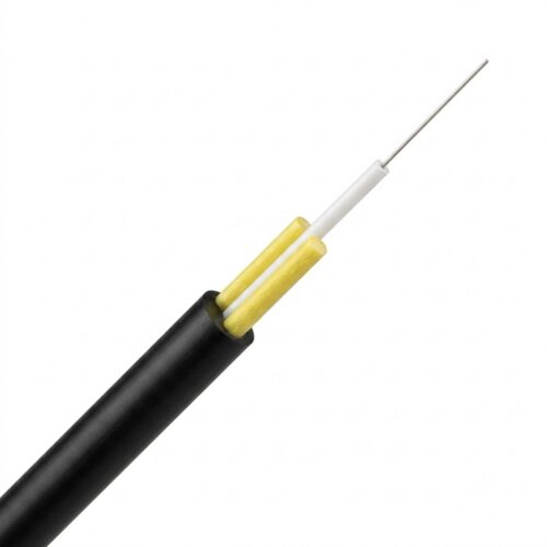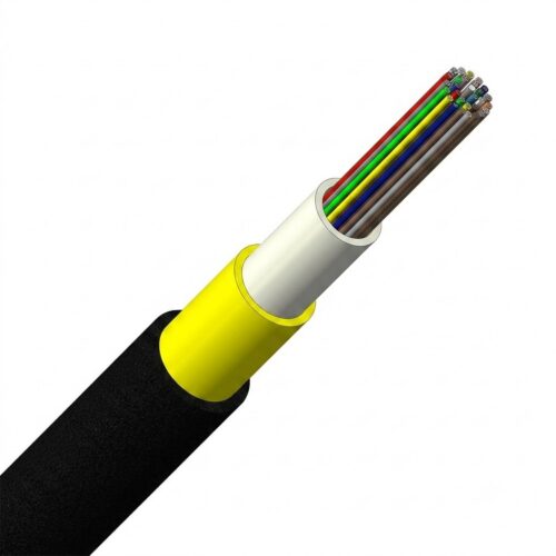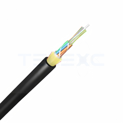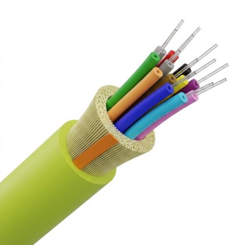
Armored Hybrid Fiber Optic Cable

Stranded Loose Tube Armored Hybrid Fiber Optic Cable
  • FRP strength and anti-buckling element
  • Robust design with moisture-proof and rodent damage.
  • Hybrid (Fibre + Copper conductor) Up to 24 fibres
  • Gelly-filled, PBT loose tubes with optical fibers
  • 2 or 4 x XLPE (Cross-linked Polyethylene) Insulated flexible conductors
  • Supports G.652D, G.657A, and G.655C single-mode fibers to meet diverse bend-insensitivity demands.
  • Ensures ultra-low attenuation characteristics (≤0.36 dB/km at 1310 nm; ≤0.23 dB/km at 1550 nm) for long-distance transmission.
  • Provides versatile deployment options for duct, conduit, and aerial installations.
  • Delivers a future-proof, robust infrastructure solution for FTTH and outdoor fiber optic networks.
  • UV stabilized PE outer jacket (other materials available)

 

https://telexc.com/contact/


Armored Hybrid Fiber Optic Cable

General Specifications
Cable Type Stranded Loose Tube Armored Hybrid Fiber Optic Cable
Construction Type Corrugated Steel Armor
Subunit Type Gel-filled
Jacket Material PE (Polyethylene)
Jacket Marking Feet/Meter
Total Conductor Count 2
Total Fiber Count 2-24
Dimensions
Conductor Gauge 16 AWG 14 AWG 12 AWG 10 AWG 8 AWG
Copper Wire Spec. 2*1.5 mm² 2*2.5mm² 2*4.0mm² 2*6.0mm² 2*8.0mm²
FRP Central strength member Diameter 2.4±0.1mm (0.094±0.004 in)
Sheath Thickness Nominal 2.1 mm (0.083 in), Minimum 1.9 mm (0.075 in)
Diameter Over Jacket 11.6 mm (0.457 in) 12.5 mm (0.492 in) 14.6 mm (0.575 in) 15.7 mm (0.618 in) 16.9 mm (0.665 in)
Mechanical Specifications
Minimum Bend Radius, loaded 232 mm (9.134 in) 188 mm (7.402 in) 219 mm (8.622 in) 236 mm (9.291 in) 254 mm (10.000 in)
Minimum Bend Radius, unloaded 174 mm (6.850 in) 250 mm (9.843 in) 292 mm (11.496 in) 314 mm (12.362 in) 338 mm (13.307 in)
Tensile Load, Installation, maximum 1500 N (337 lbf)
Tensile Load, Operation, maximum 600 N (135 lbf)
Compression 10 N/mm | 57 lb/in
Flex 25 cycles
Impact 2.942 N-m | 2.17 ft lb
Twist 10 cycles
Optical Specifications
Fiber Type  G.652.D and G.657.A1
Attenuation, maximum 0.3 dB/km @ 1,550 nm | 0.4 dB/km @ 1,310 nm/1383 nm
Environmental Specifications
Installation temperature -30 °C to 70 °C (-22 °F to 158 °F )
Operating Temperature -40 °C to 70 °C (-40 °F to 158 °F )
Storage Temperature -40 °C to 70 °C (-40 °F to 158 °F )
Water Penetration Sample length: 3m | Water head: 1m | Time: 24h
No leakage
Water Test: IEC 60794-1-22 Method F5
 Conductor Specifications
 Conductor Cross section 1.5 mm2 2.5 mm2 4 mm2 6 mm2 8 mm2
Max. DC resistance of single conductor(20 ℃) 13.3 Ω/km 7.98 Ω/km 4.95 Ω/km 3.3 Ω/km 2.47 Ω/km
Insulation Resistance (Conductor to Metallic Members) No less than 5,000 MΩ·km (20℃)
Rated voltage  Max 110 Vdc
Isulation Material XLPE (Cross-linked Polyethylene)
Dielectric Strength, conductor to shield 5000v dc (1min)
Environmental Test Specifications
Environmental Space Duct, Aerial
Packaging and Weights
Cable weight 157 kg/km (105.499 lb/kft) 190 kg/km (127.674 lb/kft) 241 kg/km (161.945 lb/kft) 300 kg/km (201.591 lb/kft) 383 kg/km (257.364 lb/kft)

1. Aerial Installations

Power Lines: Installed along high-voltage power lines without risk of electromagnetic interference (EMI) or lightning strikes, as the all-dielectric design does not conduct electricity.

Telecommunications Towers: Connects aerial towers to deliver reliable data transmission over long distances.

2. Outdoor Backbone Networks

Long-Distance Communication: Forms the core of long-distance fiber networks across remote or rural regions due to strong environmental resistance and durability.

Inter-City Links: Connects neighboring cities to provide high-speed, uninterrupted communication for telecom operators and ISPs.

3. Rural & Harsh Environments

Rural Telecommunications: Ideal for aerial deployment where underground trenching is too costly or difficult due to terrain.

Extreme Weather Zones: Built to withstand high temperatures, extreme humidity, and intense UV exposure without degradation.

4. Transportation & Transit Systems

Rail Networks: Supports communication between railway stations and control centers without interference from high-voltage electrification systems.

Highway Monitoring: Powers roadside traffic monitoring, emergency communication points, and surveillance cameras.

5. Industrial & High-Risk Facilities

Factories & Plants: Ensures stable data transmission in factory environments heavy with electrical noise.

Oil & Gas Fields: Eliminates spark risks caused by metallic components in volatile or hazardous environments.

6. Urban Infrastructure

Smart Cities: Connects urban monitoring networks, traffic control systems, and public Wi-Fi infrastructure requiring fast, dependable connectivity.

Q: What is a Hybrid Fiber Optic Cable?

A: A hybrid fiber optic cable integrates two distinct transmission media within a single outer jacket: glass optical fibers (for high-bandwidth, long-distance data) and insulated copper conductors (for low-voltage DC electrical power).

Q: What is the technical difference between a Hybrid Cable and a Composite Cable?
  • Answer:

    • Hybrid Cable: Combines two fundamentally different transmission media (optical fibers + copper power lines).

    • Composite Cable: Contains different specifications of the same medium (e.g., a mix of single-mode and multi-mode optical fibers).

    • Note: In many commercial sales catalogs, these terms are used interchangeably. Always verify the physical specification sheet (Fiber core count + Copper AWG gauge) rather than relying on the product title.

Q: How far can a Hybrid Fiber Optic Cable deliver power and data?
  • Answer: Data transmission distance is determined by the fiber core (single-mode OS2 can reach tens of kilometers). Power transmission distance is limited by copper wire gauge (AWG), remote device power consumption (Watts), and voltage drop. Under a standard 48V–57V DC supply:

    • 18 AWG: Supports low-power endpoints (~15W IP cameras) up to 150 meters (500 feet).

    • 16 AWG: Supports mid-power endpoints (~30W PoE+ access points) up to 300 meters (1,000 feet).

    • 12 AWG / 14 AWG: Supports high-power endpoints (60W–90W PTZ cameras or Wi-Fi 7 APs) up to 300 to 600 meters (1,000–2,000 feet).

Q: Does the electrical current in the copper conductors cause interference with the fiber?
  • Answer: No. Optical fibers transmit data using light photons through glass, making them inherently immune to Electromagnetic Interference (EMI) and Radio Frequency Interference (RFI) generated by the adjacent copper power lines.

Q: How does a Powered Fiber Cable System work for remote devices?

Answer: The central headend feeds DC voltage into the hybrid cable’s copper lines and optical data into the fiber strands. At the far end, the cable connects to a remote hybrid media converter/extender box. This unit regulates the incoming DC power, converts the optical signal to Ethernet data, and outputs standard IEEE 802.3at/bt Power over Ethernet (PoE/PoE++) via standard RJ45 ports to power end devices like cameras or access points.

Q: How is a Hybrid Fiber Optic Cable terminated and spliced in the field?

Answer: At the enclosure or breakout box, the outer jacket is stripped to separate the optical fibers from the copper conductors. Fiber strands are spliced or field-terminated with connectors (LC/SC) into an optical patch panel. The copper conductors are stripped, crimped with terminal lugs, and wired into screw/clamp terminal blocks connected to a DC power supply or extender module.

Engineered for Reliability, Built for Trust

At Telexc, we don’t just supply hardware—we secure your global network deployment. Operating from China’s premier industrial clusters and the Tianjin logistics hub, we act as your private supply chain control tower, ensuring engineering precision and traceably consistent quality for every aerial installation.

Our Core Advantages

  • Full-Scenario Aerial Compatibility: We seamlessly bridge the gap between OSP fiber infrastructure, FTTH networks, and aerial deployment scenarios. Every component is structurally engineered to work harmoniously together, drastically increasing on-site installation efficiency.
  • Strict Engineering Standard Alignment: Our technical design loops strictly align with international benchmarks, including IEC, ITU-T, and IEEE standards. This ensures our hardware excels under extreme environmental stresses—from intense UV exposure to heavy wind and ice loads.
  • Independent Multi-Stage Quality Control: We act as your eyes on the ground. From raw material stress simulations to finished product compliance, our dedicated QC team performs rigorous multi-stage audits so you receive exactly what your engineers approved.
  • Optimized Logistics & Flexible Partnerships: Leveraging the logistics power of the Tianjin port, we guarantee reliable transit, competitive factory-direct structures, and transparent milestone tracking to keep your network projects moving forward without compromise.