Fiber Optic Fast Connectors
Fiber Optic Fast Connector for FTTH Networks
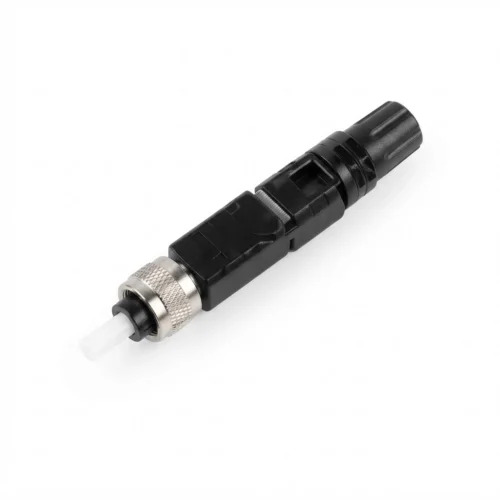
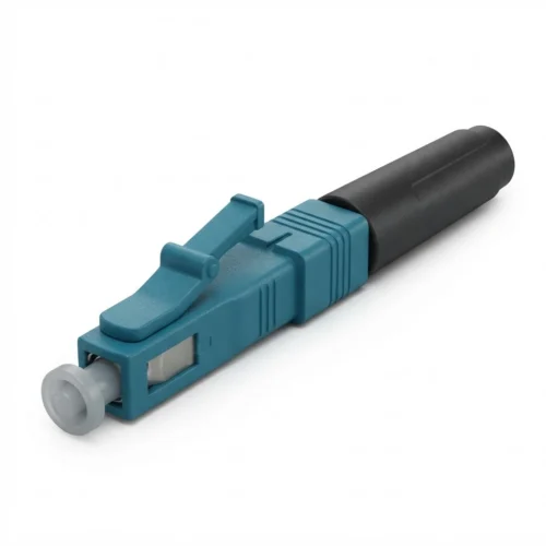
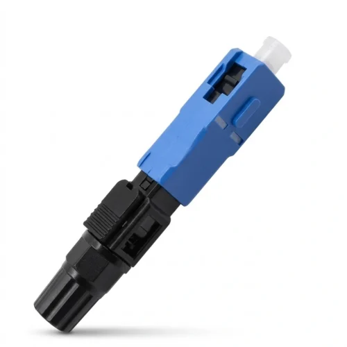
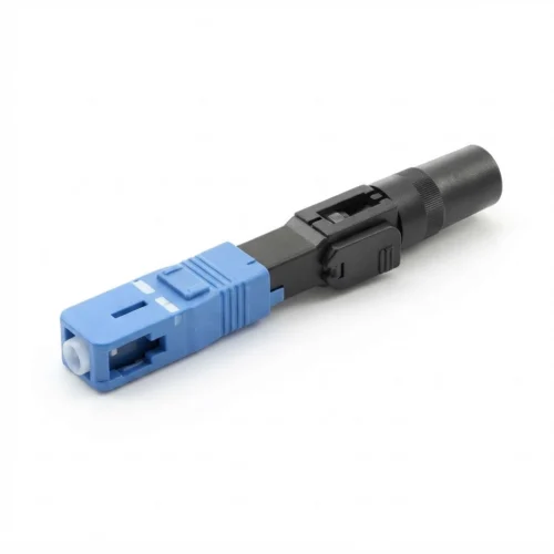
A fiber optic fast connector delivers quick mechanical termination in the field. It terminates drop cables and indoor lines without on-site epoxy or polishing. Field technicians complete each termination in about 2 minutes. This tool supplies a reliable fiber connection for high speed internet access across fiber to the premises and passive optical networks. It pairs a factory-cleaved fiber stub with an internal mechanical splice and ceramic ferrule. This setup links distribution network lines directly to the subscriber junction box.
…Fiber Optic Fast Connector for FTTH Networks
A fiber optic fast connector delivers quick mechanical termination in the field. It terminates drop cables and indoor lines without on-site epoxy or polishing. Field technicians complete each termination in about 2 minutes. This tool supplies a reliable fiber connection for high speed internet access across fiber to the premises and passive optical networks. It pairs a factory-cleaved fiber stub with an internal mechanical splice and ceramic ferrule. This setup links distribution network lines directly to the subscriber junction box.
What Is a Fiber Optic Fast Connector and How It Works
A fiber optic fast connector is also called a quick connection or field-assembled optical connector. It replaces slow multi-step field splicing. Standard terminations require manual epoxy injection, oven heating, and hand polishing. In contrast, this component moves all delicate polishing steps into a clean factory.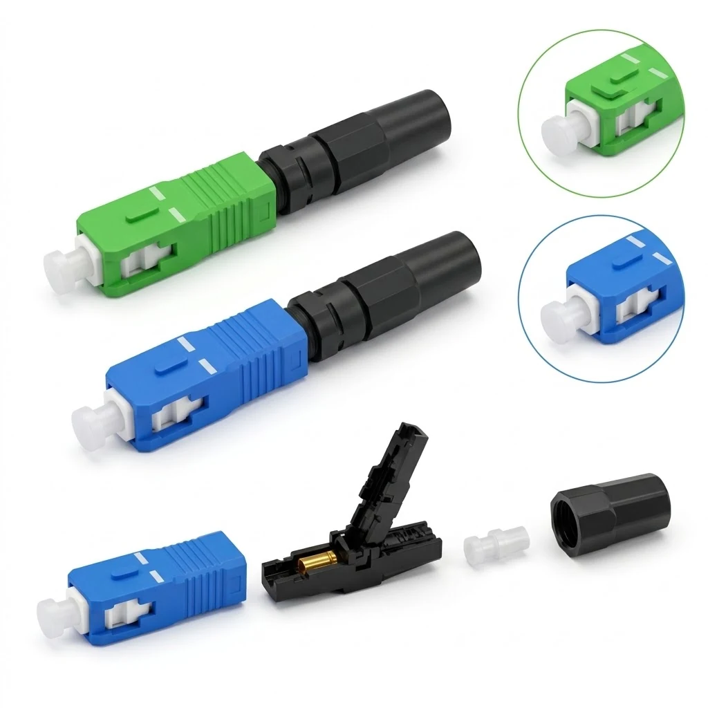
The device works through an internal V-groove mechanical splice. A pre-embedded fiber stub rests inside a ceramic ferrule. The back end of this stub extends into an alignment V-groove. Factory index-matching liquid fills this groove.
The field termination follows clear mechanical steps:
- Strip, clean, and cleave the incoming glass fiber to length.
- Push the fiber through the rear guide channel into the V-groove until it hits the pre-embedded stub.
- The index-matching liquid bridges small gaps between both glass cores. This liquid matches the refractive index of glass and stops light reflections.
- Close the mechanical crimp cover, slide collar, or cam lever. This step locks the glass in place under firm spring pressure and opens a steady light path.
Internal Structure and Key Parts
A fast connector contains several mechanical parts:
- Pre-Polished Ceramic Ferrule: Holds the factory-ground single-mode or multimode fiber stub. Ferrule concentricity measures <= 1 um to keep core alignment exact.
- Internal Alignment V-Groove: A micro-groove that centers the cleaved field fiber against the factory stub.
- Index-Matching Liquid: Pre-filled liquid inside the V-groove that limits optical return loss and prevents signal light loss.
- Wedge Clamp Mechanism: Holds the V-groove open during fiber insertion, then clamps down on the bare fiber.
- Outer Housing and Latch: Standard shells (such as SC or LC) that snap right into optical adapters.
- Cable Clamp and Boot: Grips the cable jacket, buffer tube, and strength yarn to resist strong cable pull.
Main Types of Fast Connectors
Fast connectors divide into two build designs: pre-embedded and straight-through.
Pre-Embedded Optical Fiber Fast Connectors
The pre-embedded design includes a factory-ground fiber stub inside the ceramic ferrule. The mechanical joint sits inside the internal V-groove:
- Produces typical insertion loss <= 0.3 dB (high-grade units <= 0.1 dB; maximum cap <= 0.5 dB).
- Reaches return loss >= 45 dB (UPC type >= 50 dB; APC angled polish >= 60 dB).
- Reduces reliance on field cleave flatness because the front mating face is factory-polished.
- Serves as the primary option for indoor drops, hallway lines, and FTTH networks.
Straight-Through Connectors
Straight-through connectors use a dry mechanical body without an internal stub or matching liquid:
- The field fiber passes completely through the ceramic ferrule to mate inside an adapter.
- Fiber cladding variations, clamp pressure, cut length, and endface quality alter performance.
- Poor field cuts cause loss spikes and lower return loss.
- Suits quick emergency fixes and temporary links; unsuited for large FTTH rollout projects.
Interface Formats and Cable Fit
- Connector Types: SC (standard push-pull type for FTTH drops) and LC (compact body for dense patch racks).
- Fiber Modes: Single-mode (9/125 um) for long-haul routes and multimode (50/125 um) for local office backbones.
- Supported Cables: Fits 250 um bare fiber, 900 um tight buffer, 2.0 mm and 3.0 mm round cords, and 2.0 x 3.0 mm flat FTTH drop cables.
Technical Specifications and Working Parameters
Key optical and physical performance values include:
- Insertion Loss: Typical <= 0.3 dB; high-grade lines <= 0.1 dB; maximum limit <= 0.5 dB.
- Return Loss: UPC polish >= 50 dB; APC angled polish >= 60 dB (baseline limit >= 45 dB).
- Working Wavelength: 1310 nm and 1550 nm.
- Ceramic Ferrule Concentricity: <= 1 um.
- Working and Storage Temperature: -45 deg C to 85 deg C (-40 deg F to 185 deg F). [Needs manual confirmation: verify whether specific production lots follow standard commercial -40 deg C to +75 deg C or extended industrial -45 deg C to +85 deg C limits].
- Mechanical Life: Supports up to 10 clamp re-entries; supports up to 500 adapter plug cycles.
Applications in Network Topology
The field assembly design supports many network layouts:
- FTTH and FTTP Drops: Terminates flat drop cables at subscriber homes, desk ONTs, and wall outlets.
- Corridor and Building Racks: Terminates branch optic cables run through risers and hallway boxes without power cords or fusion tools.
- Fiber to the Node (FTTN) Links: Provides rapid cross-connect points where optic cables run toward neighborhood cabinets before feeding older copper wire or coaxial cables.
- Passive Optical Networks (PON): Connects lines between central office optical line terminals and subscriber drop boxes.
- Field Repairs and Testing: Connects test gear and repairs cut lines in manholes or dirty outdoor job sites where fusion sets cannot run.
Selection Criteria for Field Work
Evaluate these practical factors when choosing field connectors:
- Endface Polish (UPC vs. APC): Pick SC/APC (green body, 8-degree angle) for CATV, RF overlay, and PON links needing return loss >= 60 dB. Pick SC/UPC (blue body) for basic digital internet.
- Cable Fit: Check that the rear boot fits the target cable size: 250 um fiber, 900 um buffer, 2.0 mm / 3.0 mm round cord, or 2.0 x 3.0 mm drop cable.
- Internal Build: Select pre-embedded connectors for permanent home drops to maintain steady light loss through hot and cold weather.
- Connector Reuse: Confirm that the internal clamp allows technicians to reset the wedge up to 10 times during field checks.
Step-by-Step Installation Procedure
[Slide Boot] --> [Strip Jacket] --> [Clean Glass] --> [Cleave Core] --> [Seat Fiber] --> [Lock Clamp] --> [Screw Boot]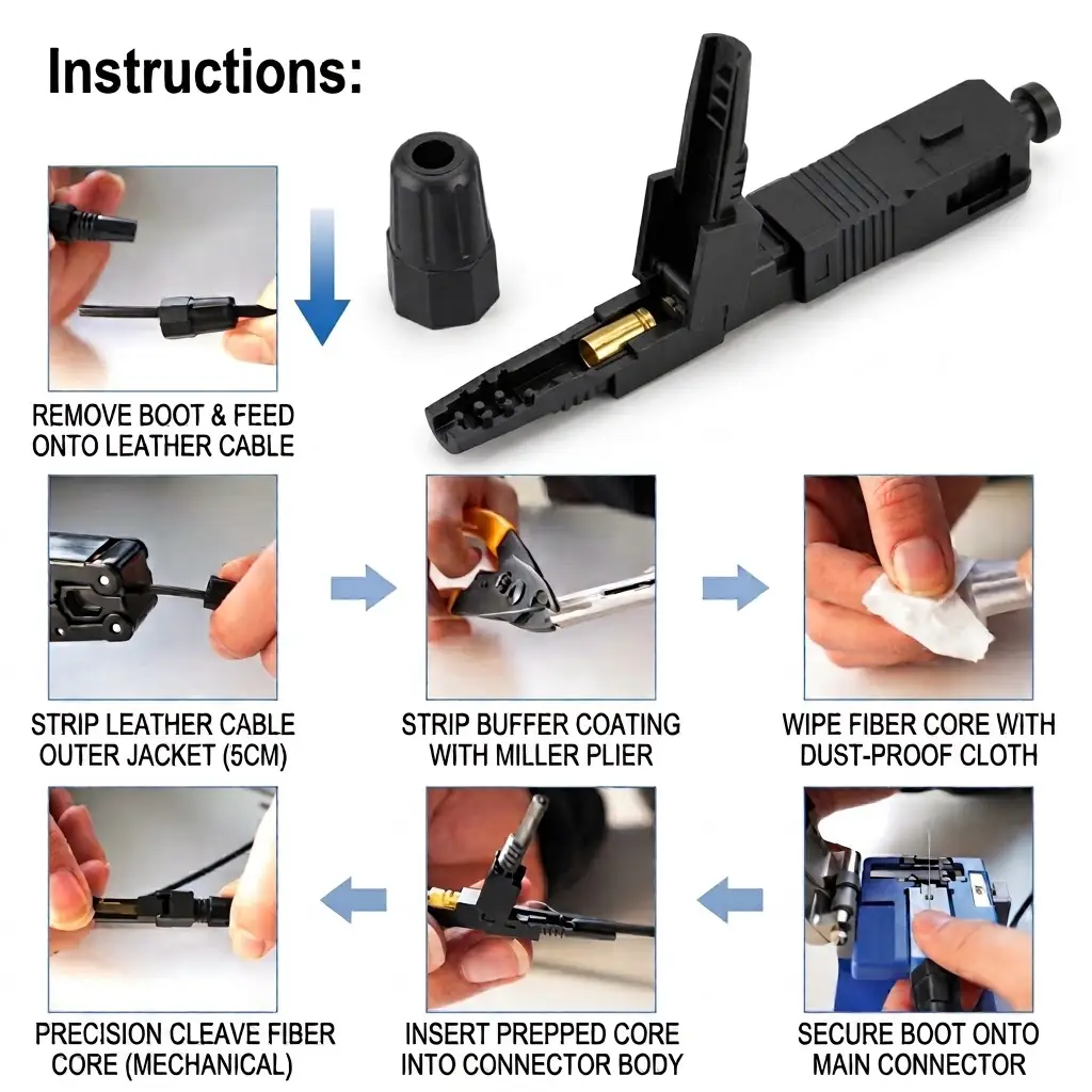
- Prepare cable and tools: Slide the tail boot and rear nut over the cable. Set out strippers, a cleaver, alcohol wipes, and 99% alcohol.
- Strip outer jacket: Strip about 50 mm (5 cm) of outer sheath from the drop cable with the flat-cable stripper. Strip the 250 um coating down to the bare glass using precision pliers.
- Clean bare glass: Clean the bare fiber with an alcohol wipe to remove acrylic dust. Do not touch the clean glass with bare hands.
- Cleave optical fiber: Lay the fiber into the cleaver jig. Cleave the glass to the length marked on the guide tool.
- Route and insert: Guide the cleaved fiber into the rear hole of the body. Slide the fiber into the V-groove until it stops against the stub and bows out slightly behind the clamp.
- Secure mechanical clamp: Hold that slight fiber bow to confirm glass contact, then press the crimp cover down to lock the bare core.
- Seal and assemble: Screw the rear boot onto the connector body to clamp the cable sheath and strength yarn. Snap the outer cover in place. Keep the dust cap on until final plug-in.
Field Maintenance and Troubleshooting
- High Insertion Loss (> 0.5 dB): Points to a bad cleave angle, glass dust, or a gap at the stub. Open the wedge, pull out the fiber, clean, re-cleave, and seat the fiber again.
- Low Return Loss (< 45 dB): Means the glass face is chipped or the matching liquid dried out from missing dust caps. Re-cleave the fiber with a sharp blade.
- Cable Slipping: Means the rear nut did not grip the cable jacket or yarn. Tighten the rear screw nut until the teeth hold the outer jacket firm.
Frequently Asked Questions
How does a fast connector differ from an epoxy-and-polish connector?
A fast connector contains a factory-polished ferrule and pre-embedded stub. Technicians finish it in 2 minutes using hand tools. Standard connectors demand wet epoxy, heat curing, and field hand-polishing.
Why do fast connectors show higher optical loss than fusion splices?
Fast connectors use mechanical butts and matching liquid in a V-groove, creating 0.2 dB to 0.4 dB of light loss. Fusion splicing melts glass cores together, keeping loss down around <= 0.05 dB.
Can technicians reuse a fast connector if optical tests fail?
Technicians can unlock and re-terminate pre-embedded wedge connectors up to 10 times. This allows new cleaves and re-insertion without throwing away the connector shell.
Conclusion
The fiber optic fast connector speeds up subscriber connections in FTTH projects. Factory polishing removes difficult hand work from the job site, enabling reliable 2-minute terminations. Paired with accurate stripping gauges and clean cleaves, this field connector cuts labor costs, protects optical link budgets, and maintains dependable network operation.
Showing all 5 results