Air Blown Micro Cable
Air Blown Micro Optical Fiber Cable
Air blown fiber technology, also known as jetting installation, utilizes high-pressure airflow to push optical fiber cables through microducts. As a result, the cable effectively "floats" forward during deployment. Operators blow these cables into microducts or conduits to construct critical communication infrastructure.
…Air Blown Micro Optical Fiber Cable
Air blown fiber technology, also known as jetting installation, utilizes high-pressure airflow to push optical fiber cables through microducts. As a result, the cable effectively "floats" forward during deployment. Operators blow these cables into microducts or conduits to construct critical communication infrastructure.
These ducts are typically made of High-Density Polyethylene (HDPE) or PVC, which protects the cable from mechanical damage and moisture ingress. Furthermore, this method enables simplified cable designs because tensile loads are distributed uniformly across the cable surface.
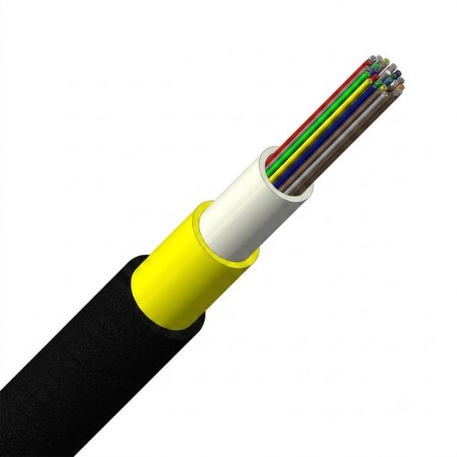
An air blown micro cable (also referred to as blown fiber, microduct cable, or air-assisted optical cable) is a lightweight, high-fiber-count cable specifically engineered for installation inside pre-laid microducts using compressed air. Featuring a small outer diameter (typically 3–10 mm), a low-friction jacket, and high tensile strength, an air blown micro cable can travel through narrow microducts over thousands of meters without physical damage.
While air blown fiber deployment requires trained personnel to operate, install, and maintain the equipment properly, high-quality micro cables feature precise diameter control, superior long-distance jetting performance, and full compatibility with standard microduct systems on the market.
Operating Principles and Physics
Understanding the physical principles behind air blown micro cable installation highlights its operational advantages over traditional methods.
Fundamental Physics
The technology operates on pneumatic conveying. Specifically, compressed air (typically 8–12 bar) injected into the microduct generates high-velocity airflow (usually 20–40 m/s). Due to its specially formulated low-friction outer jacket, the micro cable moves through the duct like a projectile propelled by air.
During installation, the cable experiences two primary forces:
- Viscous Drag (Pushing Force): The continuous force applied by high-velocity airflow pushing the cable forward.
- Frictional Resistance: The resistance between the cable jacket and the duct wall, which is minimized by a low-friction coating (CoF < 0.15).
Consequently, the cable effectively "floats" on a cushion of air. Tensile stress is distributed evenly along the entire length of the cable rather than concentrated at the front. Therefore, technicians apply minimal pushing force (typically 5–15 kg) at the blowing machine entry point.
Key Advantages of Air Blown Fiber Technology
Compared to traditional cable pulling methods, deploying an air blown micro cable offers several significant advantages:
- Reduced Duct Space Requirements: Microducts require inner diameters of only 10–20 mm, compared to 50–100 mm for conventional conduits.
- Extended Jetting Distances: Achieving single-push distances of 1,000–2,500 meters is standard, while tandem blowing setups reach up to 5–10 kilometers.
- Lower Labor and Equipment Requirements: Installation typically requires only 1–2 technicians and a single blowing machine. Thus, it eliminates heavy winches and large pulling crews, which substantially reduces labor costs.
- Significant Capital & Material Savings: Long continuous runs reduce the number of required splices and handholes. As a result, overall civil works and material costs drop by 30%–60%.
- Fast Installation with Minimal Strain: Uniform airflow imposes minimal stress on the optical fibers, lowering damage risks along routes with multiple bends or elevations.
- Future-Proof Scalability: Network operators can pre-install empty microduct networks and blow in fiber cables as demand arises ("Pay-as-you-grow"). Therefore, expansion requires no new civil excavation.
- Seamless Overbuild Capability: Enables overlay deployment on existing network infrastructure, minimizing disruption to active services while avoiding expensive trenching fees.
Step-by-Step Installation Workflow
- Microduct Placement: Pre-install PE or PVC microducts (10–20 mm ID) in trenches, existing conduits, or aerial routes.
- Cable Setup: Load the micro cable into the blowing machine equipped with an airtight duct-sealing head.
- Air Jetting Execution: Engage the air compressor (8–12 bar) while the machine feeds the cable under optimal airflow conditions.
- Real-Time Monitoring: Continuously monitor air pressure, cable speed, and feeding tension to ensure safe installation.
- Termination: Retrieve the cable at the far end and terminate it into splice closures or optical distribution cabinets.
Primary Cable Types and Structural Configurations
1. Central Loose Tube Micro Cable (GCYFXTY Type)

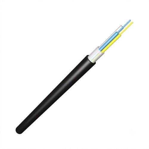
This structure features a central loose tube design with an all-dielectric (non-metallic) construction. Because it is lightweight and compact, it is optimized for tight microduct spaces and strict bend-radius conditions.
- Key Components: Water-blocking jelly-filled central tube, UV-resistant HDPE outer jacket, and aramid yarn strength members.
- Capacity & Performance: Supports up to 24 fibers, with a maximum working tension rating of 34 lbs (150 N).
2. Stranded Loose Tube Micro Cable (GCYFTY Type)

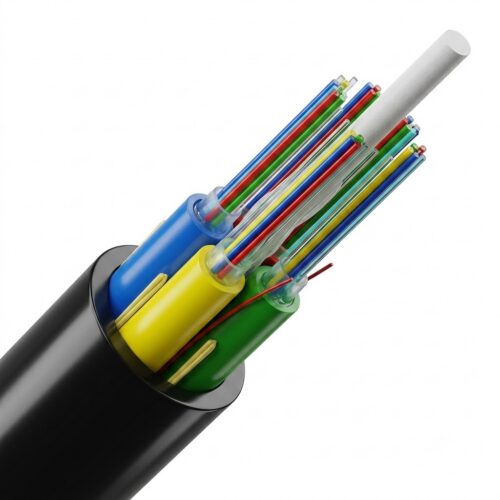
This configuration utilizes multi-loose tubes stranded around a central strength member. In addition, its all-dielectric design ensures easy installation in high-density network architectures.
- Key Components: Stranded loose tubes filled with water-blocking compound, central FRP strength member, aramid yarn reinforcement, and a low-friction HDPE outer jacket.
- Capacity & Performance: Supports up to 288 fibers, with a maximum working tension rating of 225 lbs (1,000 N).
Technical Specifications and Standards
- Fiber Types: Single-Mode (G.652D, bend-insensitive G.657A1/A2/B3) and Multi-Mode (OM3, OM4, OM5).
- Fiber Counts: 2 to 432 cores available in Central Loose Tube, Stranded Loose Tube, or Ribbon structures.
- Outer Jacket Material: Low-friction HDPE with slip-additive or nano-engineered coating (Coefficient of Friction < 0.15).
- Strength Members: Aramid yarn, glass yarn, or central FRP strength members.
- Cable Outer Diameter: 3.0 mm to 10.0 mm depending on core count and cable structure.
- Operating Air Pressure: 8 to 12 bar.
- Working Tensile Rating: 34 lbs (for Central Loose Tube designs) up to 225 lbs (for Stranded and High-Density designs).
- International Standards Compliance: Fully compliant with IEC 60794-5, ITU-T L.57, and Telcordia GR-20 standards.
Showing all 3 results