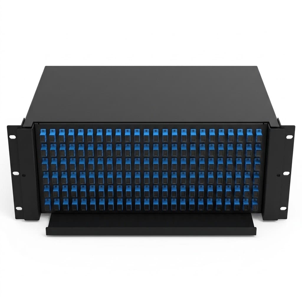
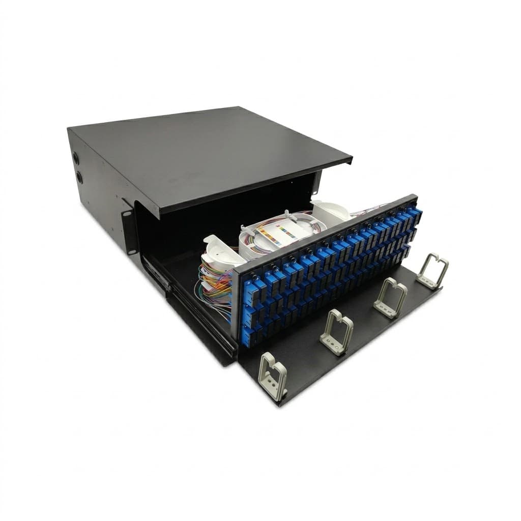
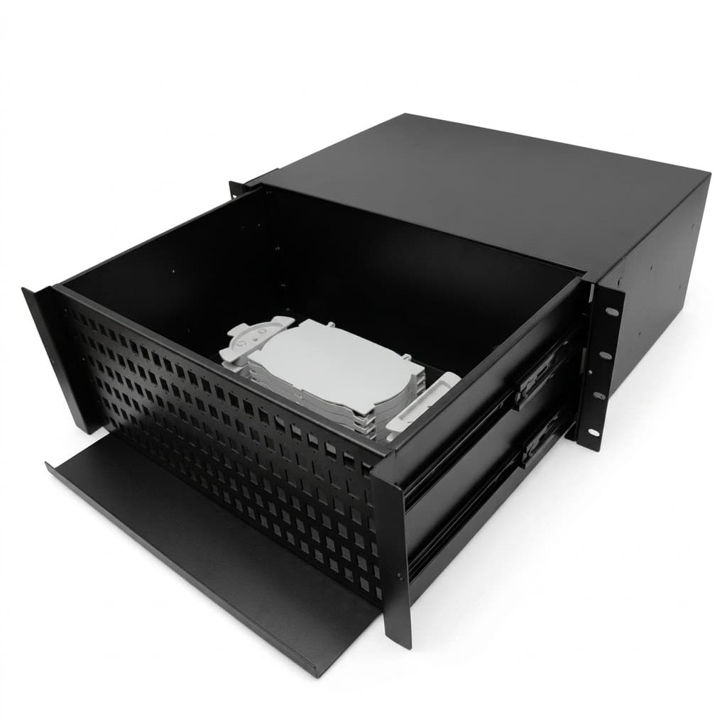
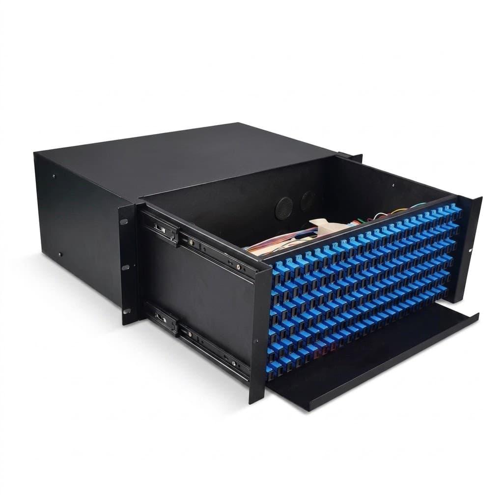
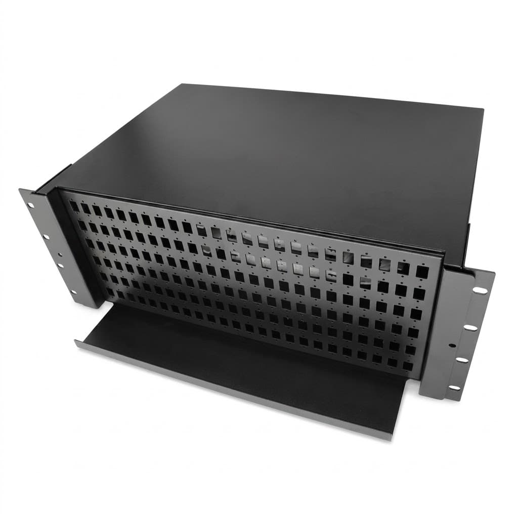
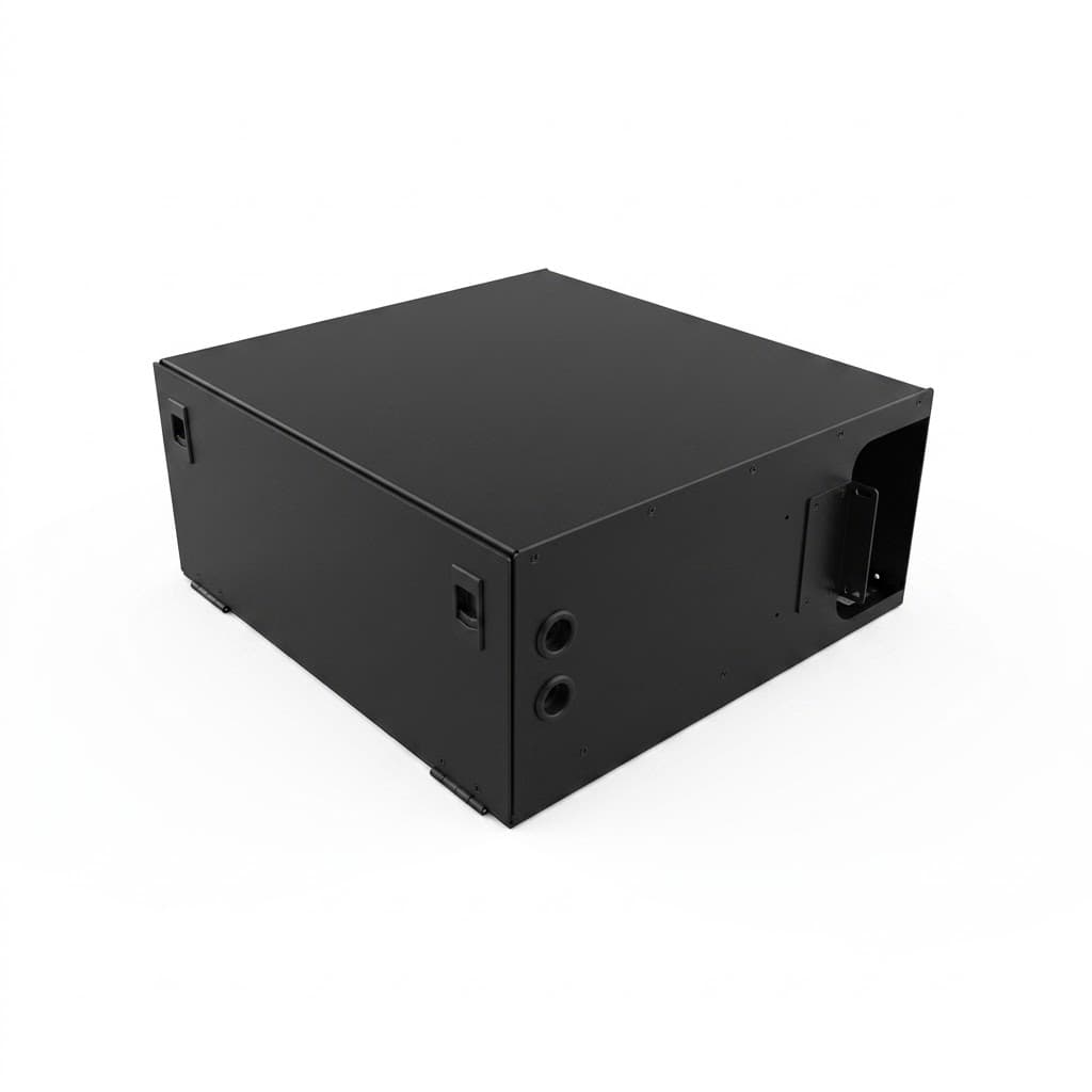

Slide Rail Rack mount patch panel
This fiber optic patch panel serves as an optical distribution unit to manage, route, and protect fiber links across FTTH networks and optical terminal distribution systems. Built from cold-rolled steel sheet with an electrostatic plastic-sprayed finish, the enclosure provides organized splicing, cross-connecting, and termination in indoor wall, terrace, and rack setups.
Key Features
-
Enclosure Material: Cold-rolled steel (CRS) sheet with electrostatic plastic-spray coating. Provides surface protection and structural rigidity for indoor telecom distribution points.
-
Internal Routing and Bend Control: Stackable, rotatable splice trays maintain a fiber bend radius greater than 37.5 mm. Prevents macrobending loss on coiled spare fibers.
-
Chassis Depth and Working Space: 400 mm deep chassis layout. Provides internal clearance for fiber routing, splicing, and adapter mounting.
-
Cable Clamping and Gland System: Adjustable clamp seal ring with reinforcement configuration. Secures various cable outer diameters tightly against mechanical strain.
-
Mounting and Disassembly: Integrated hanging pothook design. Simplifies installation, positioning, and unmounting on indoor surfaces.
-
Environmental Sealing: Indoor-grade seal configuration. Blocks dust and prevents water ingress in indoor distribution environments.
Product Configuration
The unit accommodates modular cassettes and supports multiple density configurations depending on rack height and chassis setup:
-
2U Enclosure Capacity: Up to 192 splice cores maximum.
-
3U Enclosure Capacity: Up to 288 splice cores maximum.
-
4U Enclosure Capacity: Up to 384 splice cores maximum.
-
Modular 12-Tray System: 12 modules housing 12 splice trays; each 12-fiber group operates independently for modular maintenance and staged expansion.
Technical Specifications
-
Product Type: Fiber optic patch panel / indoor optical distribution enclosure
-
Body Material: Cold-rolled steel (CRS)
-
Surface Finish: Electrostatic plastic spraying
-
Chassis Depth: 400 mm
-
Fiber Splice Capacities:
-
2U: Up to 192 cores
-
3U: Up to 288 cores
-
4U: Up to 384 cores
-
-
Modular Architecture: 12-module / 12-tray design (12 fibers per independent group)
-
Minimum Fiber Bend Radius: > 37.5 mm inside splice trays
-
Cable Port Entry Diameter: 25 mm cable input (accepts distribution and feeder cables with clamping)
-
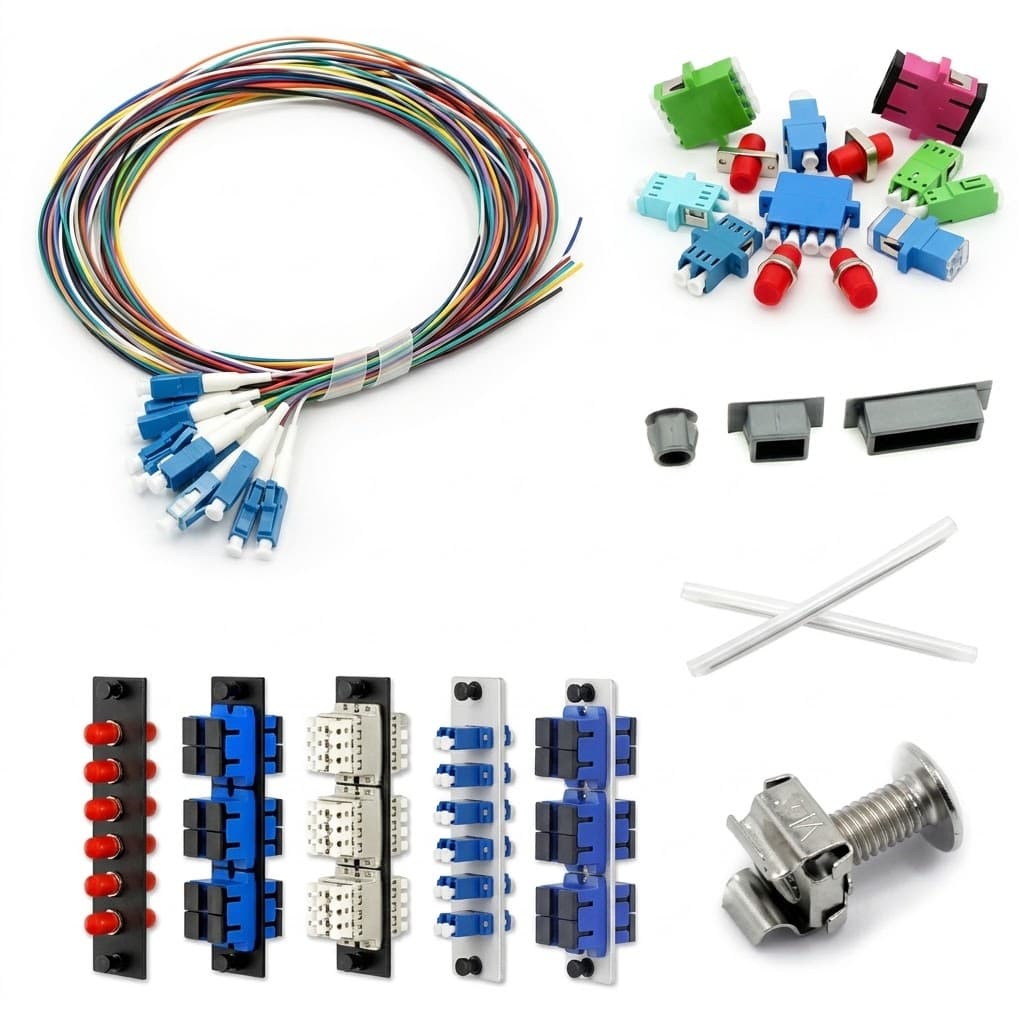
Compatible Optical Adapters: SC, LC, FC, ST, MPO, E2000
-
Operating Temperature Range: -40 deg C to +70 deg C
-
Mounting Formats: Indoor wall-mount, terrace, and standard rack integration
Applications
-
FTTH Distribution Points: Termination and link distribution for customer-drop and feeder subsystems.
-
Indoor Telecommunications Rooms: Unheated distribution spaces and structured cabling nodes.
-
Cross-Connect and Patching Fields: High-density interconnect points requiring modular 12-fiber isolation.
Selection Considerations
-
Rack Unit Profile vs. Port Density: Select between 2U (192-fiber), 3U (288-fiber), or 4U (384-fiber) variants based on port count and rack availability.
-
Connector Interface Requirements: Match front interface cutouts to project adapter standards (SC, LC, FC, ST, MPO, or E2000).
-
Cable Ingress Sizing: Verify feeder and distribution cable diameters align with the 25 mm entry ports and adjustable clamping rings.
FAQ
-
What adapter types can be loaded into the enclosure?
The chassis supports SC, LC, FC, ST, MPO, and E2000 adapter configurations.
-
What is the maximum operating temperature for this unit?
The enclosure operates from -40 deg C to +70 deg C, allowing deployment in unheated equipment rooms.
-
How are fibers organized inside the splice trays?
The system uses stacked, rotatable splice trays that enforce a bend radius greater than 37.5 mm, organized into 12 independent 12-fiber modular groups.
Choosing the right fiber optic patch panel ensures reliable link protection, structured cable management, and smooth network expansion across all FTTH distribution stages.