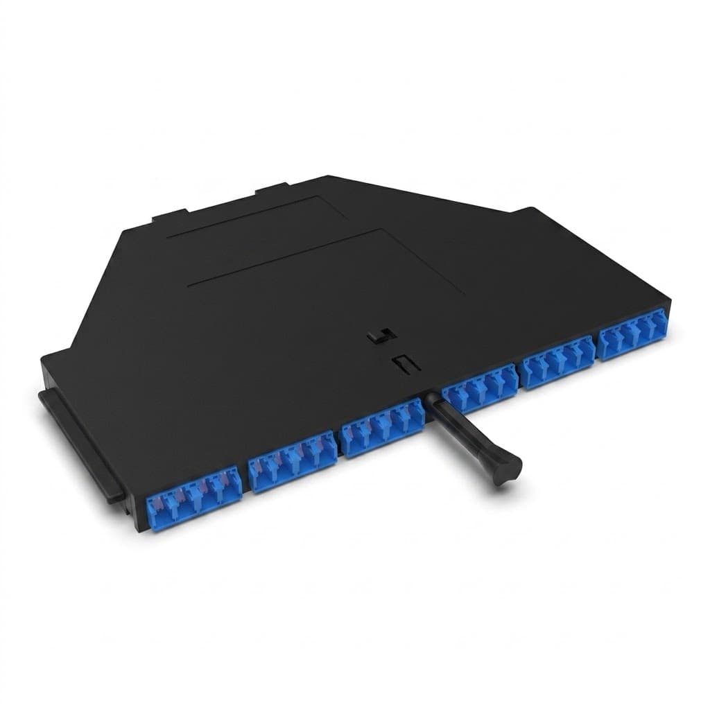
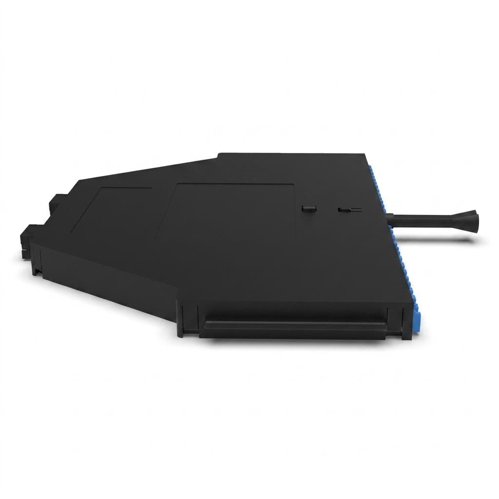
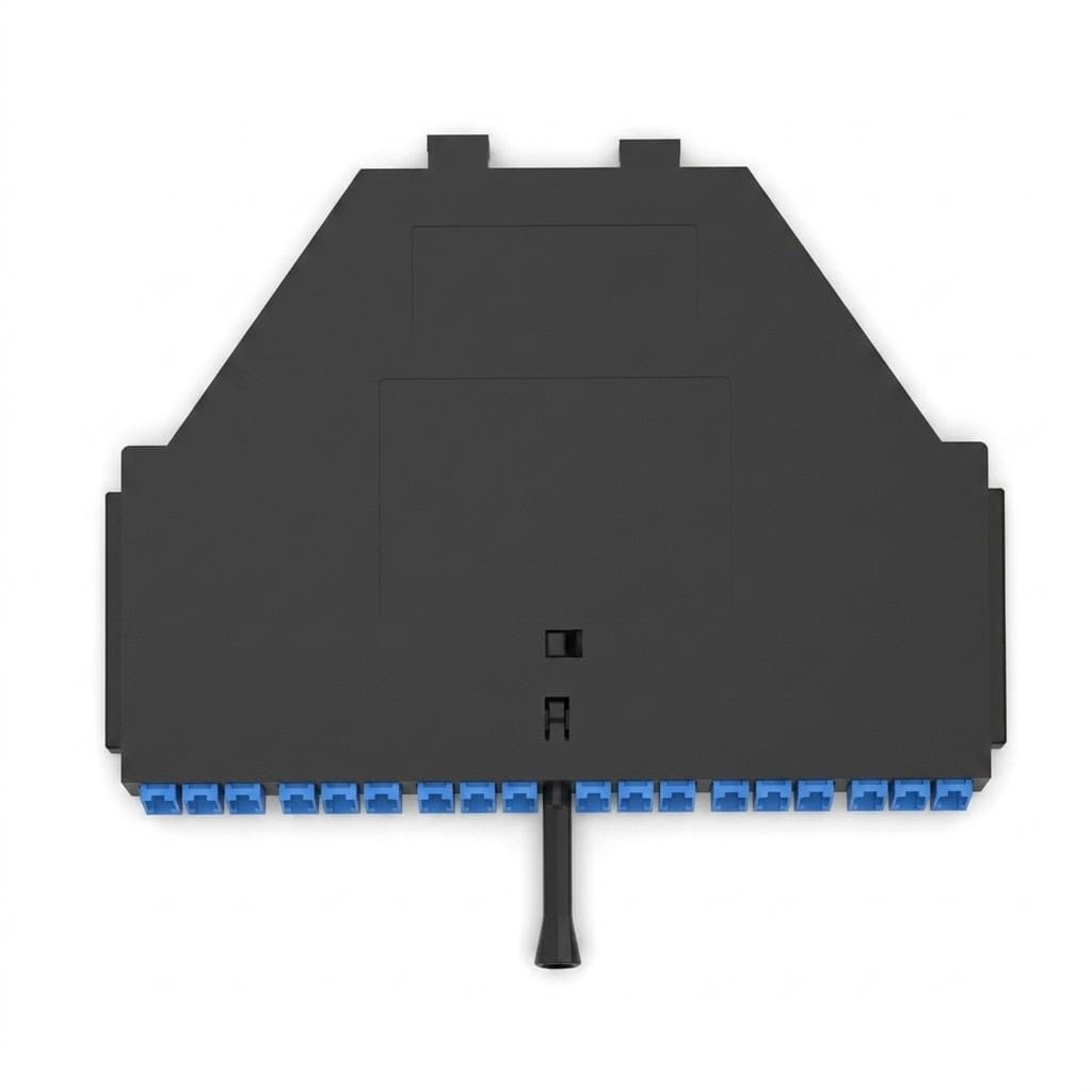
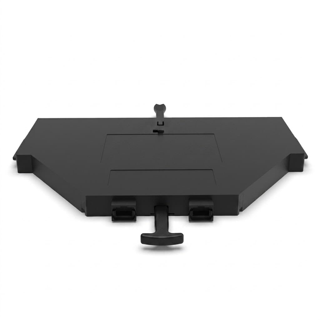
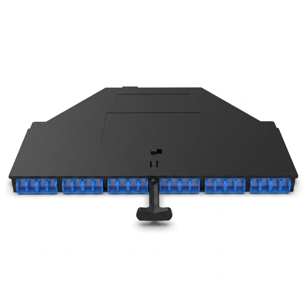
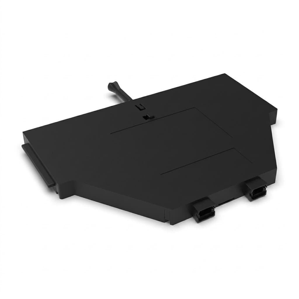
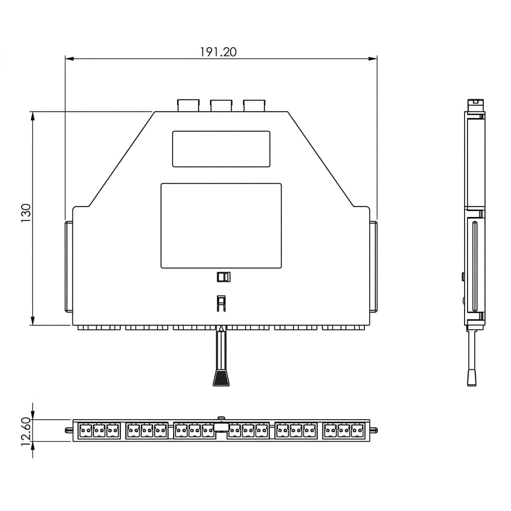

24 Fiber MPO-LC Module Transition Cassettes
The 24 fiber MPO-LC module transition cassette provides pre-terminated breakout transitions between backbone trunks and active equipment ports. Designed for direct insertion into high-density panels, this factory-terminated unit eliminates on-site fusion splicing to shorten installation schedules and control labor expenses. With support for standard and low-loss single ferrule interfaces, it serves as a reliable link for structured cabling architectures running up to 40G/100G transmission rates. For the 40G to 10G version, each cassette can hold 3x 8f MPO Base-8 LC fanouts, while the 100G to 10G version can hold 1x 24F MPO Base-24 LC fanout.
Key Features
-
Factory Pre-Terminated Assembly: Integrates internal fanouts to transition trunk connectors to front-facing LC or SC patch ports without field termination.
-
Integrated Shuttered Adapters: Features internal dust-proof and laser-safe front LC adapters to protect optical interfaces from particulate contamination.
-
Standard and Elite Performance Tiers: Offers standard and low-loss Elite connector options to satisfy strict link-loss power budgets.
-
Standardized Fiber Polarity Management: Supports Method A, Method C, and Universal Bx options aligned with TIA/EIA-568-C.3 network standards.
-
Regulatory Compliance: Complies with RoHS, REACH, and SvHC directives with conflict-free raw materials.
Product Configuration
The modular chassis footprint fits standard high-density sub-racks, enabling scalable network expansion across multi-tenant and enterprise spaces.
-
Chassis Density: Each compatible 1U panel accommodates up to 96 fiber terminations.
-
Fiber Count Options: Available in 24-fiber factory-configured capacities.
-
Optical Fiber Types: Configurable with standard single-mode and multimode optical glass.
-
Polarity Configurations: Available in TIA/EIA-568-C.3 Polarity A, Polarity C, or Universal Bx.
Applications
-
Data Center Infrastructure: Spine-and-leaf fabrics, enterprise data halls, and co-location facilities.
-
Telecommunications Networks: Central office distribution and carrier-grade optical transport links.
-
Enterprise LAN and Campus Backbones: Structured distribution links connecting main and intermediate cross-connects.
-
Broadband Optical Access: High-density distribution points within passive optical networks.
-
High-Speed Transceiver Links: Interconnects transceivers in SFP, QSFP, and CFP form factors.
-
Bandwidth Migration Paths: 40G-to-10G and 100G-to-10G port breakout distribution schemes.
Selection Considerations
Network engineers selecting a breakout cassette should evaluate several system-level requirements:
-
Fiber Polarity Scheme: Match cassette polarity (Method A, Method C, or Universal Bx) to the existing trunk cabling method to maintain proper optical transmit-to-receive paths.
-
Optical Loss Allocation: Select Elite connector options when total link loss budgets are limited by extended link lengths or cascaded patching tiers.
-
Fiber Mode Compatibility: Verify that internal glass matches external patch cords and backbone trunks (Single-mode vs. Multimode).
-
Patch Panel Form Factor: Ensure compatibility between the HD MP4 footprint and the deployed 1U or multi-U rack enclosures.
Frequently Asked Questions (FAQ)
Q: What is the main difference between an MPO cassette and an MPO breakout cable?
A: An MPO cassette is a rigid, panel-mounted module designed for structured patching within rack enclosures, providing better port labeling, protection, and scalability for frequent moves/adds/changes. An MPO breakout cable is a direct fan-out assembly better suited for simple, direct equipment-to-equipment connections without panelization.
Q: Should I choose Male (Pinned) or Female (Unpinned) rear MPO adapters for the cassette?
A: Standard MPO cassettes generally feature Female (Unpinned) internal connectors or adapters to accept Male (Pinned) MPO trunk cables. Always ensure a pinned connector mates with an unpinned connector to avoid ferrule damage or signal misalignment.
Q: How do I select the right polarity (Method A, Method C, or Universal Bx)?
A: Polarity cannot be chosen in isolation; it must align with your total channel design (trunk cables, patch cords, and optical transceivers). Method A uses straight-through wiring with A-to-B patch cords, Method C uses flipped pairs, and Universal Bx simplifies deployment by allowing identical patch cords at both ends.
Q: What is the difference between Standard and Elite (Low-Loss) versions?
A: Standard cassettes feature maximum insertion loss of <= 0.75 dB (MPO) and <= 0.30 dB (LC), with average losses around 0.18 – 0.25 dB. Elite (Premium) versions offer ultra-low insertion loss with maximum limits down to <= 0.35 dB (MPO) and <= 0.15 dB (LC), average <= 0.10 – 0.12 dB. Elite cassettes are recommended for tight optical loss budgets in high-speed (40G/100G/400G) or cascaded patching environments.
Q: Can this cassette support future network upgrades from 10G to 40G/100G?
A: Yes. By deploying MPO trunks and cassettes, your backbone is already high-density compatible. When migrating to 40G/100G parallel optics, you can easily swap the front LC patching layer or reconfigure the rear MPO links without replacing the main backbone cables.
Conclusion
High-density optical networks demand modular distribution hardware that simplifies field deployment and optimizes rack space. Deploying the 24 fiber MPO-LC module transition cassette provides structured cabling networks with a modular, factory-terminated breakout solution for up to 100G architectures. By eliminating field splicing, protecting mating interfaces with shuttered adapters, and supporting high-density 96F 1U deployments, this optical cassette reduces field labor while maintaining strict network performance standards.