
Demand for helical deadends continues as more utility operators and network planners replace bolted and multi-part tension sets with tool-free alternatives. Helical deadends for OPGW terminate and secure OPGW cables at transmission towers and substations. They consist of preformed helical wires that wrap around the OPGW cable. The helical wires tighten around the outer surface when tension is applied to the cable. It creates a strong grip without the need for the cable to be mechanically clamped. The deadends transfer mechanical tensile load from the OPGW to the supporting structure. Helical deadends anchor OPGW cables at strain towers, corner towers, and terminal towers. The complete helical deadend set can include inner-layer reinforcing rods, a thimble, a shackle, a link plate, and grounding fittings. The final configuration depends on cable diameter, rated tensile strength, tower type, and project drawings. They maintain cable tension, improve connection stability, and support line reliability.

Helical Deadend for OPGW
Helical Dead-end for OPGW anchors optical ground wire at strain, corner, and terminal structures. It works as part of ADSS & OPGW Hardware systems and helps transfer line tension across a wider cable contact area. The preformed helical rod design supports fast installation, stable grip, and long-term outdoor performance.
Key Features
- Designed for OPGW cable tension and anchoring
- Suitable for strain, corner, and terminal towers
- Connects with ADSS & OPGW Hardware systems
- Preformed helical rods provide stable cable grip
- Helps distribute axial load across the cable surface
- Inner reinforcing rods help protect the OPGW structure
- Aluminum-clad or galvanized steel wire options available
- Supports quick hand installation without special tools
- Visual inspection helps confirm installation quality
- Works with shackles, thimbles, link plates, and grounding fittings

Components and structure of helical deadends for OPGW
Helical deadends for OPGW cables secure the cable to a transmission tower while maintaining its mechanical, electrical, and optical performance. These components work together to offer mechanical performance, cable protection, and electrical and optical performance. These components include:
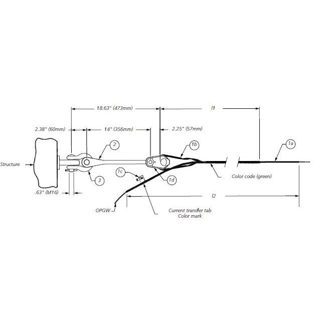
- Outer helical rods—these come as a set of preformed wires shaped to match the OPGW cable diameter. Their design allows the distribution of the gripping force over a long section of the cable instead of concentrated at a single point. The rods provide high tensile strength, controlled helical pitch, accurate diameter compatibility, and corrosion-resistant material.
- Reinforcing rods—some dead-end designs consist of reinforcing rods between the cable and outer helical rods. The rods help distribute pressure around the cable and improve the grip. These inner rods distribute radial pressure, protect the OPGW surface, increase holding strength, and reduce localized mechanical stress.
- Dead-end eye—the thimble provides the mechanical connection between the helical grip and the tower hardware. It contains a loop through which the clevis, shackle, link, or other hardware passes through. The deadend eye transfers tensile loads from the OPGW through the deadend assembly to the transmission structure.
- Armor rods—armor rods serve around the OPGW near the termination area. They provide extra mechanical protection and help distribute contact forces between the cable and the gripping mechanisms. Armor rods protect the OPGW against abrasion, bending stress, compression, vibration, and localized loading.
- Dead-end loop—the helical rods form a controlled loop around the OPGW to determine how the tensile force moves from the cable into the fitting.
- Connection hardware—the helical deadend serves with connection hardware, including clevises, shackles, links, eyebolts, yoke plates, extension links, and fasteners.
Types of helical deadends for OPGW cables
The use of helical deadend clamps for OPGW depends on the cable’s construction, mechanical requirements, installation location, and transmission-line design. Using preformed helical rods to grip and terminate the OPGW depends on the following different designs.
Double deadend configurations
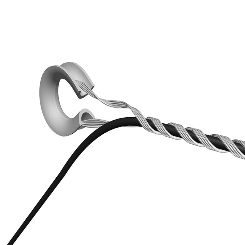
Double-ended deadends use two termination assemblies to accommodate special transmission-line structures. They serve where extra mechanical security or specific tower arrangement is necessary. This is including major angle structures, special crossings, high mechanical loading, and complex tower configurations.
Tension deadends with armor rods
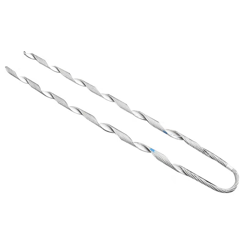
These deadends use armor rods around the OPGW before the main deadend grip is installed. The armor rods provide an extra layer of mechanical protection and distribute forces around the cable. They serve where the OPGW faces tensile forces, bending, vibration, abrasion, and mechanical stress.
High-tension OPGW dead ends
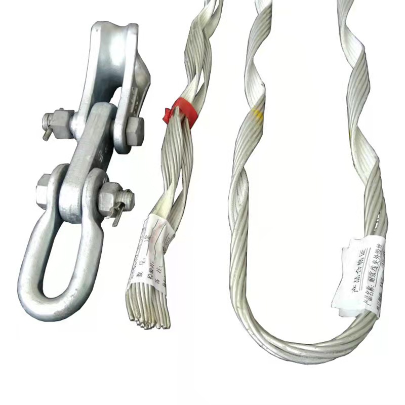
High-tension deadends serve in applications where the OPGW faces higher mechanical loads. They use reinforced helical rods and stronger attachment components to provide the required holding strength. They maintain enough mechanical strength without damaging the OPGW.
Standard OPGW helical deadends
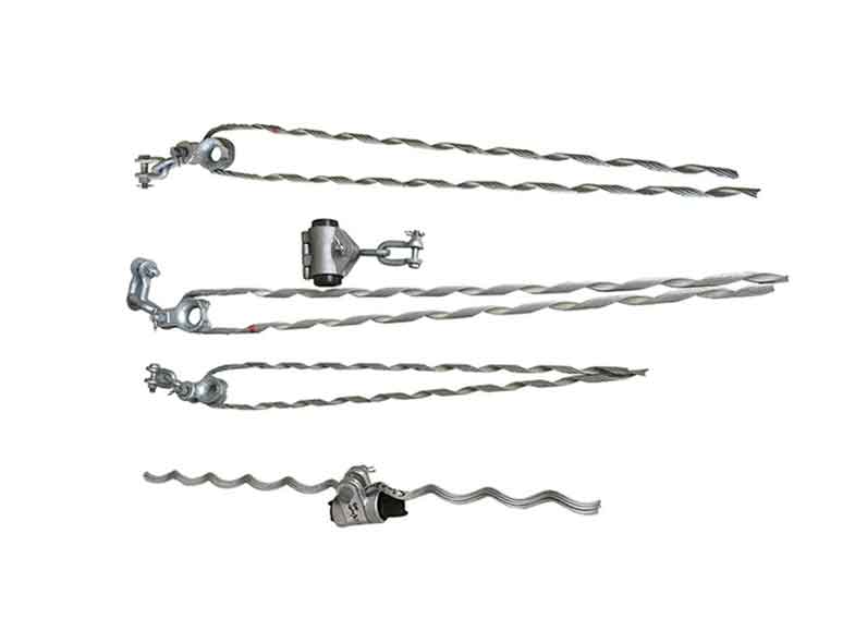
Standard helical deadends are ideal for OPGW termination points on transmission towers. They use preformed rods that wrap around the cable and transfer tensile loads to the tower through an attachment assembly. The dead end is selected according to the OPGW diameter, rated tensile strength, and manufacturer’s specifications.
The working principle of the helical deadends for OPGW
Helical deadends for OPGW provide the mechanical termination and load-transfer point between an OPGW cable and a transmission structure. OPGW cables act as lightning-protective or grounding conductors and an optical communication cable. During installation, preformed helical rods wrap around the OPGW in a specified direction. The rods should match the cable’s diameter and construction. The helical configuration provides a secure gripping force around the cable. This allows the dead end to hold the cable without depending on a concentrated mechanical clamp.
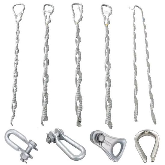
The helical deadend transfers tensile forces from the OPGW through the preformed rods and termination hardware to the transmission tower. OPGW carries optical fibers used for communication, protection, monitoring, and control of electrical networks. At a deadend structure, the deadend component secures the cable without disturbing its internal optical-fiber elements. The cable then remains mechanically supported while the optical fibers continue to provide communication between substations and other network facilities.
How to select the right helical deadend for OPGW
Utilities and operators should select the OPGW deadend depending on the cable’s mechanical, dimensional, electrical, and environmental requirements. The deadend is a system of components used to secure the OPGW cables in overhead networks. The correct helical deadend is one that matched the OPGW cable, mechanical loading, tower arrangement, electrical requirements, and operating environment. When selecting the helical deadends, consider the following factors.
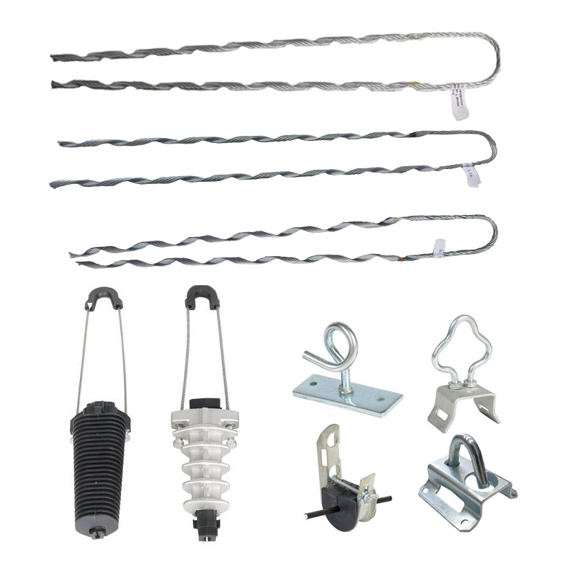
- Confirm the OPGW cable diameter—determine the exact outside diameter of the OPGW. Check strand configuration, cable construction, and the manufacturer’s cable designation.
- Check the rated tensile strength—the dead end must have enough mechanical holding strength for the OPGW’s rated tensile strength. The utility should ensure maximum tension, maximum installation tension, maximum design tension, and deadend holding strength.
- Consider the transmission-line loading—the selected deadend should account for wind pressure, snow loading, temperature variation, elevation, span length, tower angle, and sag tension conditions.
- Match the deadend to the tower configuration—the physical configuration of the transmission structure determines how the deadend connects to the tower. Consider tower type, attachment-point geometry, line angle, required connection length, shackle configuration, and link hardware.
- Verify the OPGW’s electrical requirements—operators should consider fault-current rating, short-circuit duration, electrical continuity, grounding arrangement, and bonding requirements.
- Assess optical fiber protection—the dead end should avoid compression, bonding, torsion, localized stress, or crushing of the cable.
- Select the right helical configuration—utilities need a standard deadend, a reinforced configuration, or an assembly incorporating armor rods. The fitting may also need extra reinforcement to distribute stress along the OPGW.
- Check standards and utility specifications—check the deadend against the applicable utility specifications, project requirements, and relevant industry standards. The manufacturer should offer documentation covering mechanical strength, holding strength, dimensional compatibility, material properties, electrical performance, and installation procedure.
Technical specifications for the helical deadends for OPGW
Specifications for the deadend depend on the mechanical, dimensional, electrical, material, and environmental requirements of the transmission line. OPGW combines overhead grounding and lightning protection with fiber-optic communication that demands deadends that provide reliable mechanical retention without compromising the cable.
| Type | Available Dia. of Cable Min(mm) | Available Dia. of Cable Max(mm) | Length of Helical Rods Inner (mm) | Length of Helical Rods Outer (mm) | Ref. Weight (kg) | Devastating strength (kN) |
| TF070/0880 | 7.9 | 8.8 | 1390 | 990 | 1.2 | 70 |
| TF070/1010 | 8.9 | 10.1 | 1390 | 990 | 1.3 | 70 |
| TF100/1140 | 10.2 | 11.4 | 1530 | 1110 | 1.7 | 100 |
| TF100/1280 | 11.5 | 12.8 | 1610 | 1190 | 2.4 | 100 |
| TF120/1410 | 12.9 | 14.1 | 1650 | 1230 | 2.6 | 100 |
| TF120/1550 | 14.2 | 15.5 | 1830 | 1350 | 2.9 | 120 |
| TF120/1730 | 15.6 | 17.3 | 2000 | 1470 | 3.6 | 120 |
| TF160/1920 | 17.4 | 19.2 | 2410 | 1790 | 4.7 | 160 |
| TF160/2110 | 19.3 | 21.1 | 2610 | 2010 | 5.2 | 160 |
Applications of helical deadends for OPGW
Helical deadends serve where an OPGW must be securely terminated, tensioned, or mechanically transferred to a supporting structure. They serve in transmission networks because OPGW combines fiber-optic communication with grounding and lightning protection. Common application areas include:
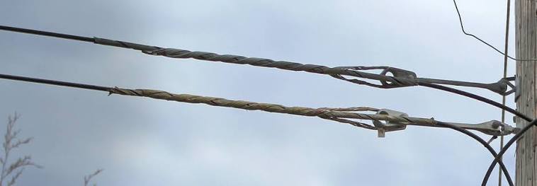
- High-voltage transmission lines—helical deadends secure OPGW at designated tension or deadend structures. They help maintain the designed OPGW tension, transfer mechanical loads to the tower, and maintain the grounding function of the OPGW.
- Dead-end and tension towers—the deadends serve where the OPGW terminated or where line tension must be transferred to the structure. They withstand the mechanical loads generated by the OPGW while providing a reliable connection to tower hardware.
- Angle towers—OPGW can experience increased mechanical loading at towers where the transmission line changes direction. The deadends serve in tension arrangements to secure the cable and transfer the resulting forces to the structure.
- Long-span transmission crossings—long spans create higher mechanical loads and more demanding sag-tension conditions. Rated OPGW deadends help secure the cable at the supporting structures on either side of the crossing.
- OPGW replacement and upgrading projects—existing transmission lines can be upgraded by replacing earth wires with OPGW. Helical deadends establish secure termination points for the replacement cable. Their design can simplify installation when the new OPGW must be integrated with existing tower hardware.
- Utility distribution and specialized overhead networks—specialized overhead communication and grounding systems use OPGW-type cables in other utility applications. The deadend selected should match the cable construction and mechanical requirements.