
Fiber Attenuators
Fiber Optic Attenuator
A fiber optic attenuator reduces optical signal power in a fiber link or free-space path. In optical networking, higher power does not guarantee better system performance.
… Load moreShowing all 2 results
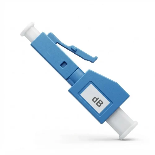
Excess light saturates receiver amplifiers and distorts waveforms. This condition raises the bit error rate (BER) and can damage sensitive photodetectors.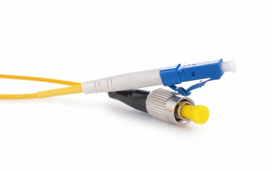
An optical attenuator introduces calibrated signal loss measured in decibels dB. This loss keeps optical power levels within the safe operating range of the receiver without changing signal wavelength or phase.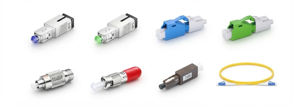
Operating Principles and Signal Thresholds
Every optical data link depends on receiver power levels for reliable data transmission. Receiver operation involves two main limits:
- Receiver Sensitivity (Lower Limit): This value marks the minimum input power required for clear signal detection. Below this level, noise interferes with the signal and BER rises. BER represents the inverse of the signal-to-noise (S/N) ratio.
- Receiver Overload (Upper Limit): This value marks the maximum input power a receiver can accept. Higher power saturates the amplifier and causes severe data errors.
The span between transmitter output power and receiver sensitivity sets the total optical power budget. The gap between sensitivity and overload defines the receiver operating range.
Singlemode laser transmitters built for long routes often overpower receivers on short cable runs. Mismatched media converters create the same problem when an optical link is too short for its optical budget. Attenuators also resolve signal issues caused by electrical impedance mismatch in adjacent driver circuits.
Attenuators also assist link stress tests. Technicians increase dB attenuation step by step until the optical link drops. This test reveals the true operating safety margin.
Specific dB values correlate directly to percentage reductions in signal power:
- 1 dB: 21% signal reduction
- 2 dB: 37% signal reduction
- 3 dB: 50% signal reduction
- 4 dB: 60% signal reduction
- 5 dB: 68% signal reduction
- 6 dB: 75% signal reduction
- 7 dB: 80% signal reduction
- 10 dB: 90% signal reduction
- 13 dB: 95% signal reduction
- 15 dB: 96.8% signal reduction
Attenuator Structure and Components
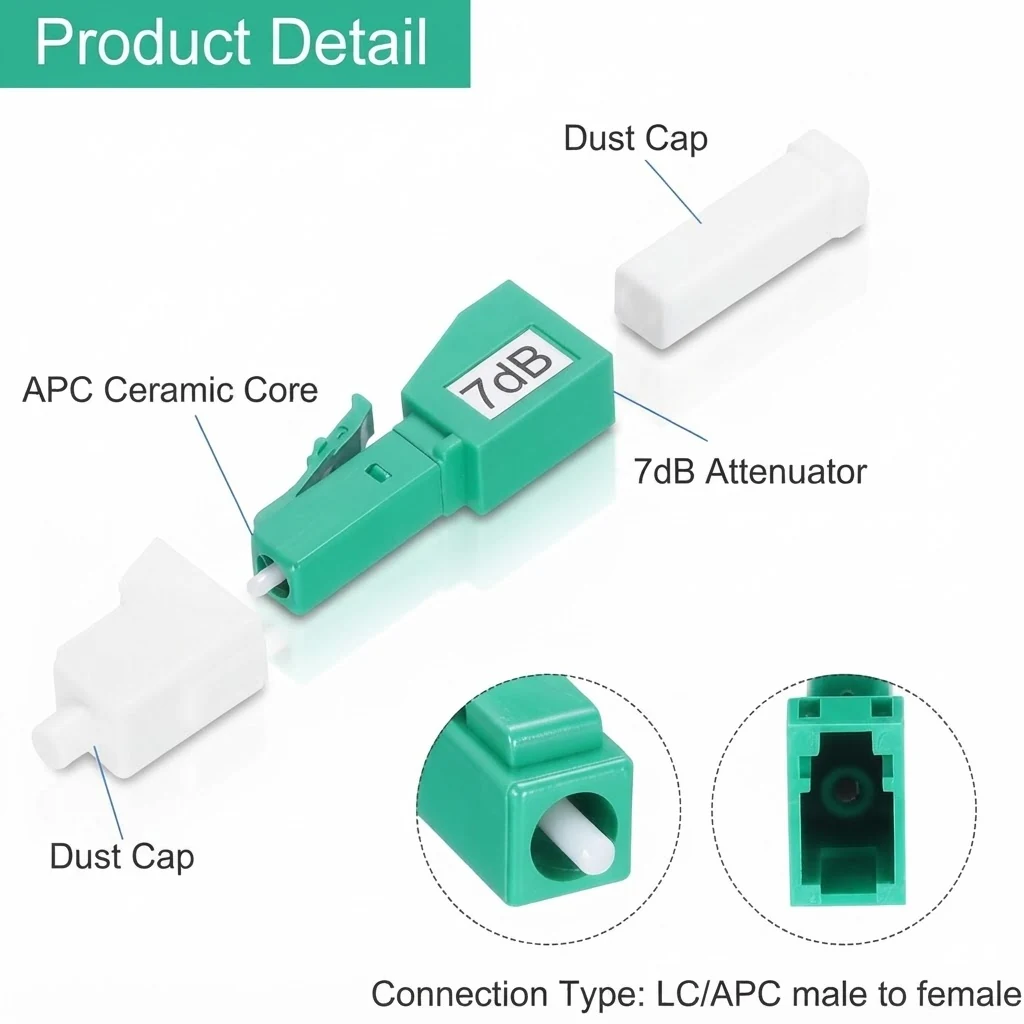
A standard attenuator includes precision alignment sleeves, internal attenuating media, and standard connector housings:
- Attenuating Core: A fixed optical attenuator uses metal-ion doped fiber or offset splices. Variable units use neutral density filters or motorized wheels. Advanced designs use MEMS mirrors, liquid crystal cells, or magneto-optic crystals.
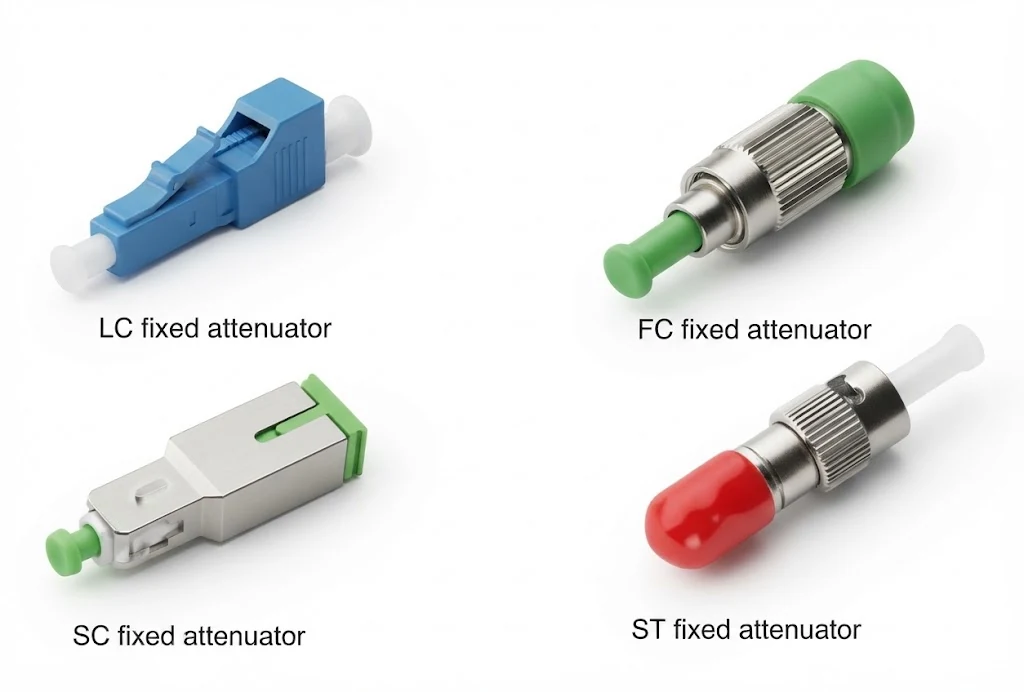
- Connector Housings: External shells match standard LC, SC, ST, FC, MU, E2000, and MTRJ interfaces.
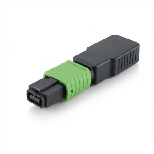
- Multi-Fiber Housings: An MPO attenuator controls 12, 24, or 32 optical fibers inside a 59.8 x 20 x 6.5 mm housing.
- Loopback Construction: A loopback attenuator with LC or SC connectors houses 900 um buffered fiber in a black shell. MTRJ and MPO loopback units omit this outer shell.
- Ferrule Endfaces: Ferrules feature Physical Contact (PC), Ultra Physical Contact (UPC), or 8-degree Angled Physical Contact (APC) polishes to minimize return loss at mating points.
Attenuation Physics and Working Principles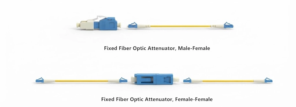
Natural fiber attenuation in an optical link comes from glass impurities, Rayleigh scattering, and cable bends. Manufactured attenuators apply specific physical methods to reduce power:
- Light Absorption (Preferred Method): Absorptive units work like sunglasses. They use doped fiber to absorb excess light and release it as low-level heat. Because absorption traps light instead of reflecting it back along the transmission line, it stops back reflections. This design prevents laser instability and stops parasitic lasing in fiber amplifiers.
- Variable Filter and Solid-State Control: Variable attenuators insert neutral density filters into the light beam. Electronic units adjust coupling efficiency through MEMS mirrors, liquid crystal cells, lithium niobate modulators, thermo-optic structures, or Faraday rotation crystals. These units provide a wide dynamic range for real world testing.
- Gap Loss and Reflection (Non-Preferred Method): Some designs leave an air gap between fiber cores or use reflective coatings. These approaches perform poorly in communications systems. Gap-loss units remain sensitive to dust, modal changes, vibration, and temperature swings. They also create high back reflections and signal dispersion.
- Wavelength Flatness: WDM and DWDM systems carry multiple channels across shared optical fibers. Quality attenuators maintain a flat attenuation curve across all operating wavelengths. A flat curve prevents channel power imbalances.
- Power Limits: Because attenuators convert light into heat, standard passive models handle modest power. Most support a few hundred milliwatts. Doped-fiber units support a maximum transmission power of 1 W. High power fiber lasers require specialized thermal components. [Needs manual confirmation: Exact maximum continuous-wave optical power rating per product SKU].
Optical Attenuator Classifications
Fixed Attenuators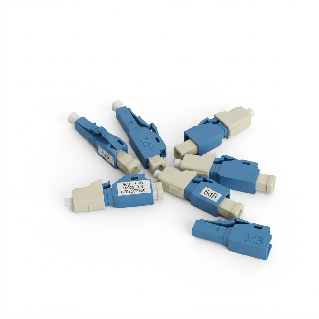
Fixed units provide a permanent attenuation level. Suppliers stock them from 1 dB to 25 dB or 1 dB to 30 dB. Common values include 1 dB, 3 dB, 5 dB, 10 dB, 15 dB, 20 dB, 25 dB, and 30 dB (sometimes written as -3 dB, -5 dB, or -10 dB).
- Plug-Style (Male-to-Female): These units carry a male plug on one side and a female socket on the other. They plug straight into receiver ports or patch panel adapters.
- Bulkhead (Female-to-Female): These units mount into patch panel cutouts and link two fiber patch cords together.
- In-Line and Embedded: Technicians build inline units directly into patch cords. Alternatively, technicians fuse embedded attenuators directly into cable spans.
Variable Optical Attenuators (VOA)
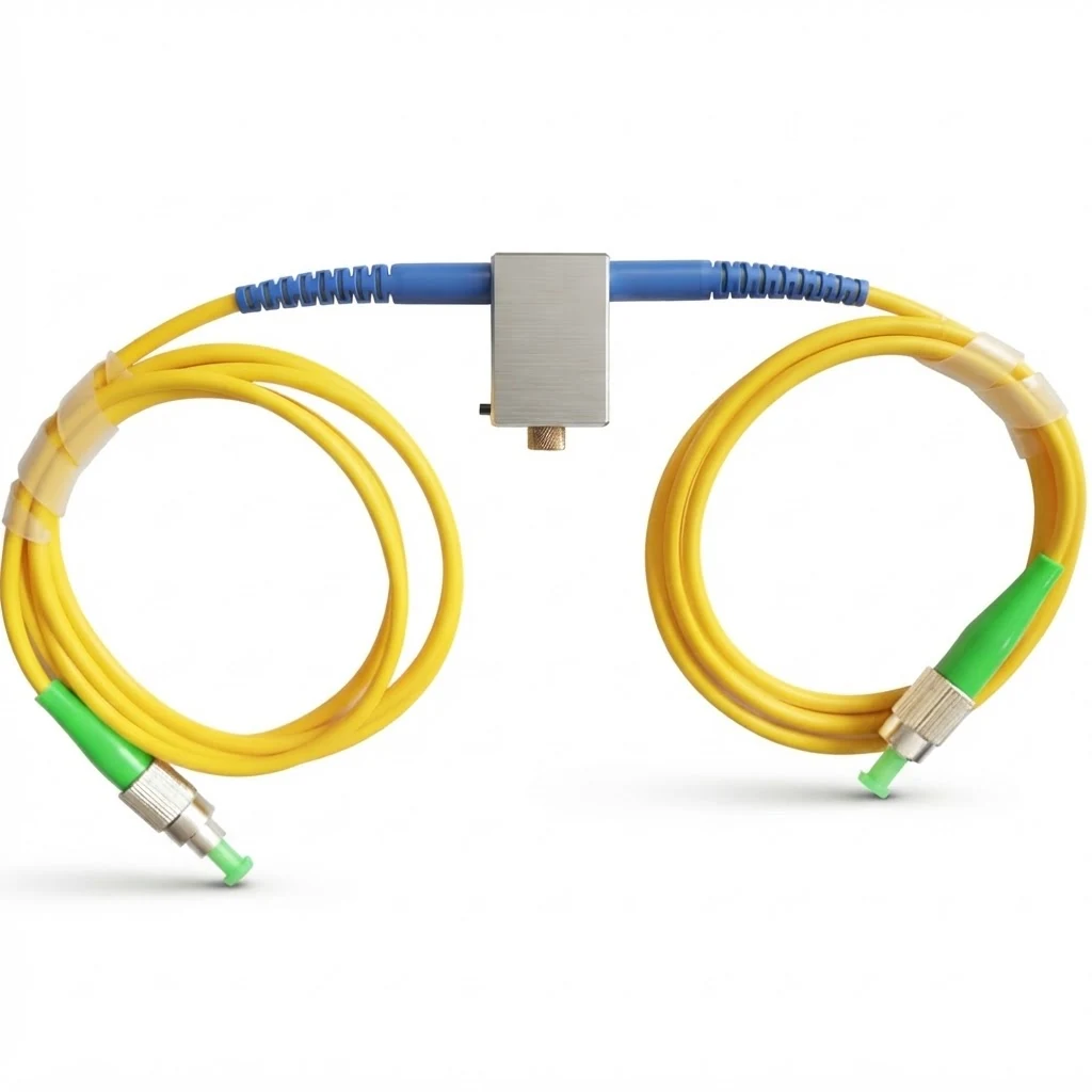
A variable optical attenuator (VOA) allows dynamic loss adjustments across ranges like 0 to 30 dB, 1 to 30 dB, or 0 to 60 dB:
- Manual VOAs: Technicians turn screws, knobs, or sliders to move internal neutral density filters. Dials provide an accuracy around +/- 0.5 dB. Precision mechanical units reach +/- 0.1 dB.
- Automatic VOAs: Systems use MEMS, liquid crystals, or magneto-optic crystals for fast power control. Magneto-optic units adjust in 0.2 ms with zero mechanical wear. Fast response matters in active networks. A delay of one microsecond can drop critical data packets.
- Benchtop Test VOAs: Test instruments use microprocessors and digital displays. Motor-driven test units automate repetitive multi-wavelength sweeps.
MPO Multi-Fiber Attenuators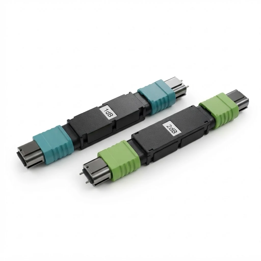
High speed data centers run MPO attenuators across 40G, 100G, 400G, and 800G parallel links. These components adjust 12, 24, or 32 fibers at once across ratings from 1 dB to 30 dB.
Loopback Attenuators
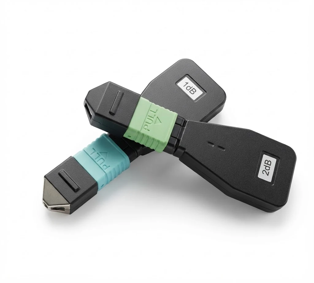
A loopback attenuator connects the transmitter port directly to the receiver port. Technicians run loopbacks during board burn-in and link troubleshooting. They come in SC, LC, FC, and MPO configurations for singlemode and multimode networks.
Fiber Type Differences
- Singlemode (SM): SM units cover 1250 nm to 1600 nm, including 1310 nm and 1550 nm. They support long-haul, metro, and short laser links.
- Multimode (MM): MM units serve 50/125 um and 62.5/125 um cores at 850 nm and 1300/1310 nm. Multimode transmitters rarely saturate receivers. Therefore, engineers rarely need MM attenuators outside test labs. Custom runs often require a 50-piece minimum order and a 2 to 4 week lead time.
Critical Technical Specifications
- Operating Wavelength: Doped singlemode units span 1250 nm to 1600 nm. General product lines cover 850 nm, 1310 nm, and 1550 nm.
- Attenuation Range: Fixed units cover 1 dB to 30 dB. Variable models cover 0 to 60 dB.
- Attenuation Accuracy:
- Singlemode fixed: +/- 0.5 dB for values up to 5 dB; +/- 10% above 5 dB.
- MPO fixed: +/- 1 dB at 10 dB or less; +/- 10% from 10 dB to 30 dB.
- Precision VOAs: +/- 0.1 dB or +/- 0.1 times the attenuation value.
- Insertion Loss: Standard VOAs show baseline insertion loss below 2.5 dB. High-grade VOAs stay below 1.0 dB. C-band tunable units reach 0.6 dB.
- Return Loss: Values exceed 45 dB on standard units. PC and UPC connections reach >= 50 dB. APC 8-degree angles reach >= 60 dB.
- Polarization-Dependent Loss (PDL): Quality designs keep polarization-dependent loss (PDL) under 0.2 dB.
- Switching Speed: Magneto-optic units respond in 0.2 ms. MEMS devices switch in microseconds to milliseconds.
- Calibration Points: Quality test attenuators store thousands of factory points to ensure linear calibration across multiple wavelengths.
Network Applications
- DWDM Channel Balancing and ROADM Systems: Attenuators support DWDM channel balancing across all wavelength channels in DWDM systems. This balance prevents channel cross-talk and distortion.
- EDFA Amplifiers: Attenuators balance multi-channel gain profiles. They keep input power inside the linear range of the amplifier.
- Short Singlemode Links, CATV, and FTTH: Attenuators prevent receiver overload on short runs between optical line terminals and customer units. Analog CATV links require high return loss to protect laser diodes.
- Data Centers: MPO attenuators protect 100G and 400G transceivers from power spikes in parallel links.
- Laboratories: Test benches use VOAs to simulate cable loss, calibrate power meters, and test transceiver limits under real world conditions.
Selection Criteria and Link Budget Calculations
Follow these steps to calculate loss and pick the right fiber optic attenuator:
1. Calculate Required Attenuation
Target the middle of the receiver operating range. Never leave received power near the receiver overload limit:
- Short Link Rule: A transmitter delivers -3 dBm, and the receiver overload threshold is -8 dBm. The link requires at least 5 dB attenuation (-3 dBm - (-8 dBm) = 5 dB).
- System Design Example:
- Transmitter Minimum Launch Output Power: 0 dBm
- Receiver Sensitivity: -30 dBm
- Receiver Overload Limit: -15 dBm
- Total Optical Power Budget: 0 dBm - (-30 dBm) = 30 dB
- Minimum Cable Plant Loss to Prevent Overload: 0 dBm - (-15 dBm) = 15 dB
- Ideal Target Receiver Input Power: -20 dBm (requires 20 dB total loss)
- Link 1 (Cable loss = 10 dB): Install a 10 dB fixed optical attenuator. (10 dB cable + 10 dB attenuator = 20 dB loss; received power = -20 dBm).
- Link 2 (Cable loss = 15 dB): Install a 5 dB attenuator. (15 dB cable + 5 dB attenuator = 20 dB loss; received power = -20 dBm).
- Link 3 (Cable loss = 20 dB): No attenuator needed.
- Link 4 (Cable loss >= 30 dB): High cable loss leaves insufficient power. Install a higher-power transmitter or an optical amplifier instead of an attenuator.
2. Match Connectors and Ferrule Polish
Match the connector to the patch panel or transceiver:
- LC: High-density equipment and SFP modules.
- SC: Telecom distribution panels and test kits.
- ST: Legacy plant hardware with bayonet locks.
- FC: High-vibration sites with threaded locks.
- MPO: High speed parallel links.
- Polish Choice: Choose UPC (>= 50 dB return loss) for standard digital links. Choose APC (>= 60 dB return loss) for CATV, RF video, and singlemode PON networks. Never mate an APC ferrule to a UPC ferrule.
3. Choose Fixed vs. Variable Units
- Fixed Units: Select fixed attenuators for permanent links with known loss. Do not stack multiple fixed units in series. Stacking adds excess back reflection and loose mating tolerances.
- Variable Units: Select a variable optical attenuator (VOA) for lab work, tuning tests, or networks with shifting optical loads.
Installation and Maintenance Procedures
Always install the attenuator at the receiver end of the fiber run. Receiver-side placement allows quick power verification with an optical power meter. It also forces any reflected light to drop along the cable before reaching the laser transmitter.
- Prepare the work area by switching off high power laser sources. Gather optical cleaning wipes, an inspection scope, and a calibrated power meter set to the correct operating wavelength.
- Inspect all attenuator ports and patch cord ferrules under the inspection microscope. Clean all mating surfaces to prevent ceramic damage and excess return loss.
- Route the patch cords inside the rack or cabinet while keeping bend radii above manufacturer limits.
- Secure the attenuator directly into the receiver port or patch panel adapter until the connector latches firmly into place.
- Splice inline attenuators into permanent outside-plant fibers with a fusion splicer, and protect the joint with a heat-shrink sleeve.
- Seal outdoor cabinet doors and enclosure lids to keep dust and moisture out. Measure received optical power with the meter to confirm power falls near the midpoint of the operating window.
Mandrel Wrap Hazard: In emergencies, some field workers wrap fiber patch cords around a pencil to induce bend loss. This practice causes severe problems. Modern bend-insensitive glass resists bend loss. In addition, the tight coil creates mechanical stress that breaks optical fibers over time. Replace temporary coils with an engineered hardware attenuator immediately.
Frequently Asked Questions
Why do fiber optic communications systems use attenuators instead of amplifiers? Amplifiers boost weak optical signals over long runs. Attenuators reduce high optical power on short spans. Without attenuation, strong laser light overloads the receiver and corrupts data transmission.
Can technicians stack multiple attenuators in a single link? Technicians can stack units physically, but best practices discourage it. Each mating joint introduces reflection, insertion loss variation, and potential contamination. Install a single attenuator with the correct dB value instead.
Why do singlemode networks need attenuators more than multimode links? Singlemode links use laser transmitters designed for long transmission distances. These lasers easily overload receivers on short links. Multimode transceivers use lower-power sources that rarely overwhelm photodetectors.
Where should an engineer install an optical attenuator? Install the attenuator at the receiver end of the link. This position allows easy testing with an optical power meter. It also dampens reflected light before that light travels back to the transmitter.
Conclusion
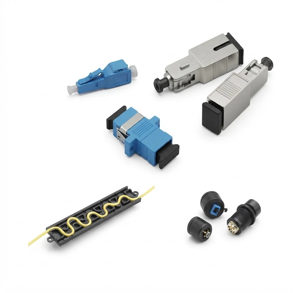
A fiber optic attenuator prevents receiver overload, stabilizes DWDM systems, and keeps bit error rates low across communications systems. By calculating link loss, matching connector polishes, and placing absorptive attenuators at receiver ports, engineers build reliable optical networks with dependable power margins.