
Fiber Distribution Box
Fiber Distribution Box
A fiber distribution box acts as the central wiring hub in a fiber optic network. Technicians also call this unit an optic distribution box. This rugged enclosure organizes, terminates, and protects thin optical fibers across local access loops.
… Load moreShowing 1–12 of 16 results
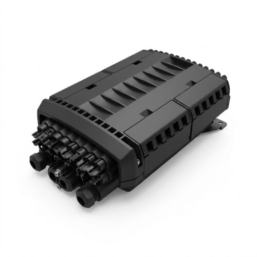
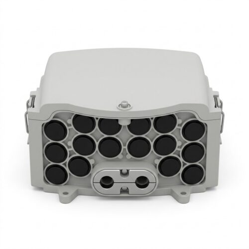
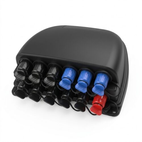
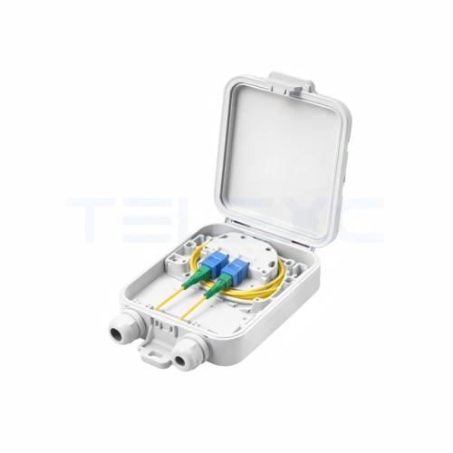
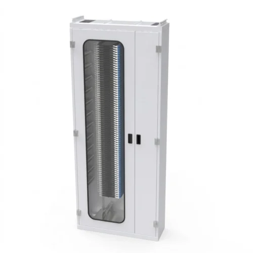
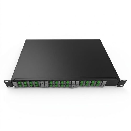
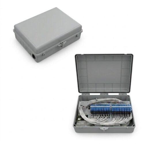
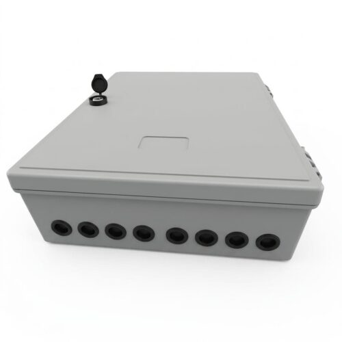
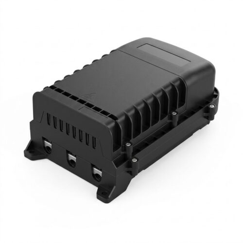
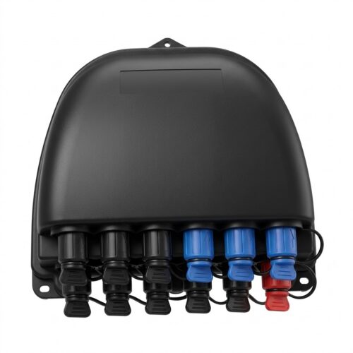
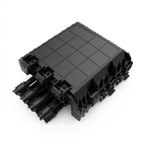
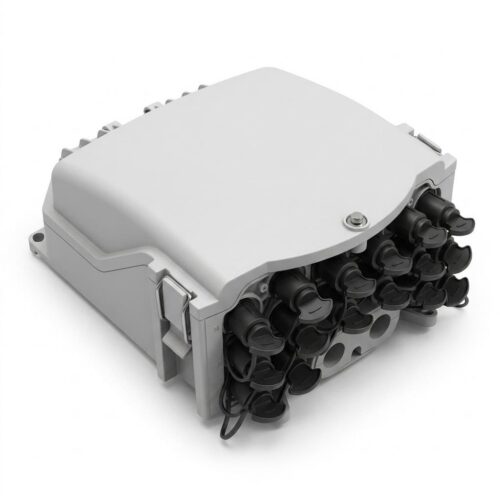
In modern fiber to the home ftth links, this box joins thick feeder fiber optic cables to flexible drop cable lines. The reliable fiber connection carries high speed optical signals straight to subscriber homes and edge nodes.
An optical distribution network connects the central office to local customer homes. Inside this plant, the fiber distribution box fdb shields each fiber splice and all optical splitters from harsh outdoor weather.
Field crews rely on these enclosures to hook up drop lines fast. The box allows crews to isolate line faults and distribute fiber lines as subscriber demand grows. Picking the right ftth fiber distribution box ensures dependable uptime across indoor and outdoor access points.
What Is a Fiber Distribution Box?
A fiber distribution box for ftth is a rugged protective housing. It holds incoming feeder lines, splice trays, connector adapters, and outgoing drop connections. The box creates a clean physical junction where a thick, high-count fiber cable breaks out into single subscriber circuits.
In standard FTTH ODN lines, the optical signal path follows a direct run:
Optical Line Terminal (OLT) → Feeder Cable → Fiber Distribution Box → Drop Cable → Optical Network Unit (ONU/ONT)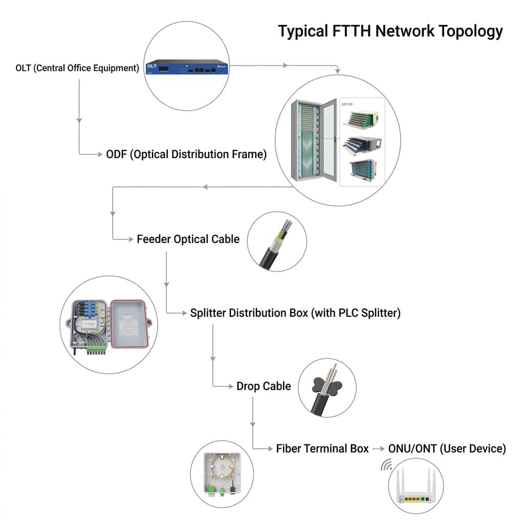
When network engineers deploy passive optical networks, they fit optical splitters right inside the tray:
Feeder Cable → FDB Box → Optical Splitters → Drop Distribution Lines → Subscriber Premises
This modular layout lets telecom teams distribute optical signals to many customer drops at once. Crews do not need to pull long, single lines back to the central exchange.
Engineering Functions of FDB
A field-grade fiber distribution box performs five basic mechanical and optical tasks.
1. Cable Entry and Strain Relief Heavy trunk lines enter through lower or side ports. Internal metal clamps grip the outer jacket and the central strength member. The clamp locks down steel wires or FRP rods. This design stops line tugs, pole vibration, and wind loads from pulling on the glass inside.
2. Fusion Splice Protection The internal splice tray holds each fiber splice safe and straight. Molded channels hold plastic heat-shrink sleeves firmly in line. Smooth routing tracks keep the loop wide. This stops micro-bend signal loss after splicing.
3. Circuit Distribution and Patching The unit routes feeder lines to local drops using three common setups:
- Adapter Panel Patching: Technicians plug SC or LC drop lines directly into mating sleeves.
- Pigtail Splicing: Factory-polished pigtails fuse straight to raw trunk fibers.
- Direct Fusion Splice: Trunk fibers weld straight to drop lines inside internal trays.
4. Splitter Integration A dedicated fiber distribution box with plc splitter houses compact steel tubes or cassette units. Common split sizes include 1×4, 1×8, 1×16, and 1×32. Packing passive splitters in the box saves space. It also cuts out the need for bulky underground splice vaults.
5. Environmental and Physical Shielding Bare glass snaps under tight bends, damp air, and fine dust. A sealed shell locks out heavy rain, salt fog, sun rays, and direct impacts.
Primary Mechanical Components
Every fiber distribution box relies on modular internal parts to make field tasks fast.
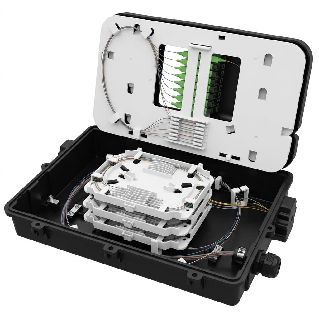
- Enclosure Body: High-impact outer shell fitted with weather gaskets and a lock. It shields internal optical parts from rain, dust, and physical impact.
- Fiber Splice Tray: Hinged plastic cassette that rotates upward for multi-tier access. It secures fusion splice protection sleeves and stores bare fiber slack.
- Adapter Panel Strip: Removable mounting plate that holds rows of singlemode SC/APC or LC/UPC mating sleeves. It creates a standardized interface for customer drop patch cords.
- Fiber Routing Baskets: Molded base guide rings and side channels. They direct fiber slack paths and maintain a strict 30 mm minimum bend radius.
- Cable Glands and Entry Seals: Threaded compression nuts and stepped rubber grommets. They seal cable entry ports against dust, bugs, and water.
Types of Fiber Distribution Boxes
Hardware vendors manufacture diverse fiber optic distribution boxes to match specific field environments.
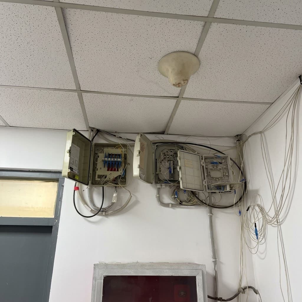
- Indoor Fiber Distribution Box: Lightweight ABS or polycarbonate plastic enclosure. It mounts inside building riser shafts, utility closets, and basement telecom rooms.
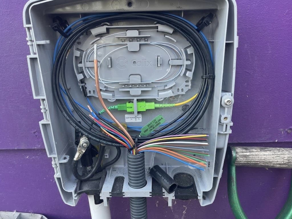
- Outdoor Fiber Distribution Box: Heavy-duty, UV-resistant polymer or coated steel cabinet with silicone seals. It mounts on outdoor utility poles, exterior masonry walls, and street curbs.
- Wall Mounted Unit: Flat-back enclosure bolted directly to interior walls or exterior building facades. It provides distribution for multi-tenant residential units.
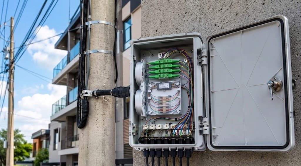
- Pole-Mounted Unit: Weatherproof chassis attached to round concrete or treated wood poles with steel bands. It supports overhead distribution lines along aerial ftth network routes.
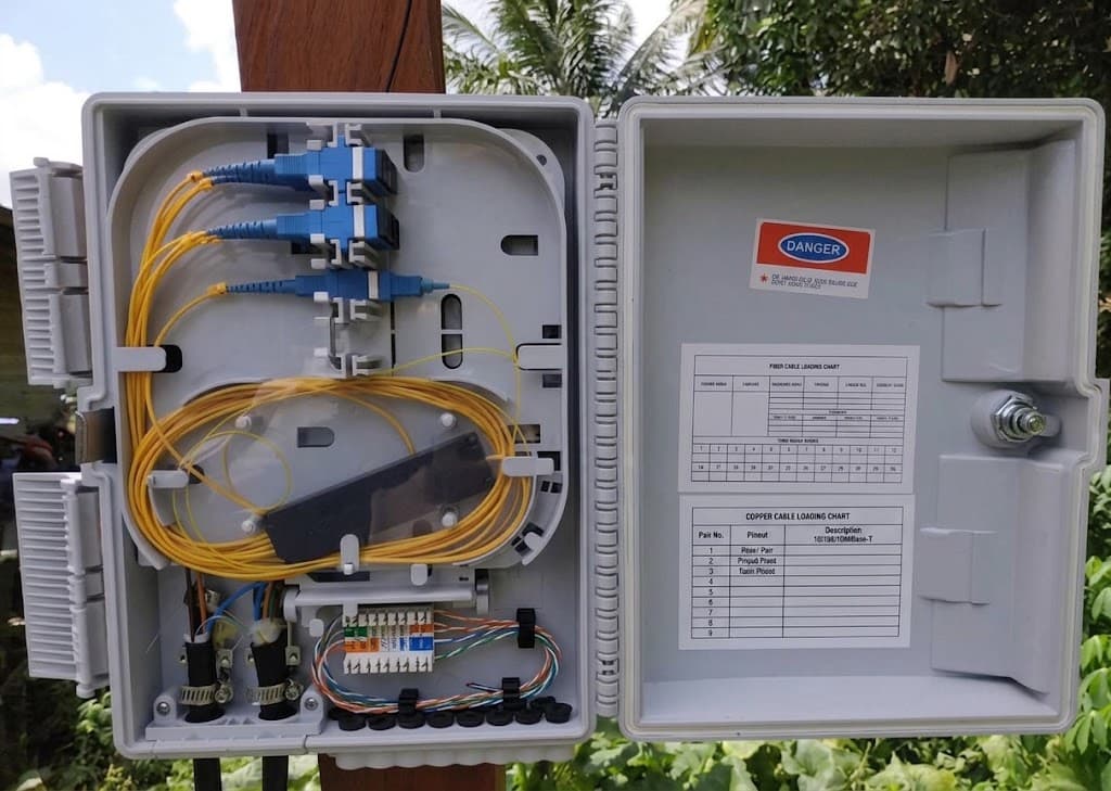
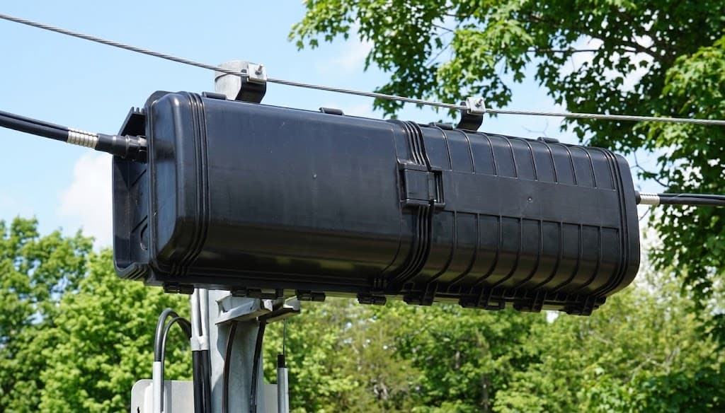
- Strand-Mounted Unit: Aerodynamic, lightweight box hung directly on aerial messenger support wires. It provides drop connections along open aerial spans.
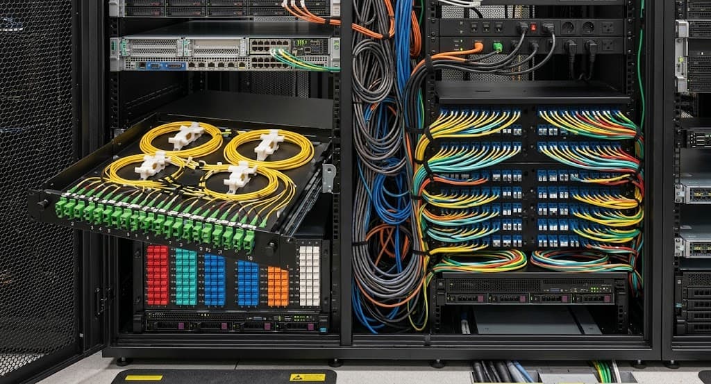
- Rack-Mounted Panel: Standard 19-inch metal distribution frame mounted in equipment racks. It manages high-density cross-connect lines in a carrier data center.
Enclosure Material Standards
The raw box material sets the physical strength, working life, and weather resistance.
- ABS Plastic: Low-cost polymer offering simple moldability and low weight. It works best in clean, temperature-controlled indoor communication closets.
- PC/ABS Blend: High-impact thermoplastic alloy combining rigid strength and thermal resistance. It serves well across both indoor and outdoor access terminals.
- SMC Composite: Sheet Molding Compound fiberglass-reinforced polyester with high tensile strength. It resists solar UV radiation, chemical vapors, and heavy mechanical impacts along industrial routes.
- Stainless Steel: Grade 304 or 316 metal alloy providing extreme anti-corrosion performance. It serves harsh coastal ports, chemical plants, and heavy industrial yards.
- Cold-Rolled Steel: Electro-galvanized sheet metal finished with an electrostatic powder coating. It delivers strong anti-theft protection in shared public basements.
Ingress Protection Ratings
Outdoor enclosures require formal Ingress Protection (IP) ratings certified under the IEC 60529 standard.
- IP20 Enclosure: Basic dust barrier with zero moisture protection. It installs exclusively in dry indoor office rooms.
- IP54 Enclosure: Sealed chassis blocking light dust and water splashes. It fits indoor building basements and covered service corridors.
- IP55 Enclosure: Weatherproof shell resisting low-pressure water sprays from any angle. It serves sheltered outdoor walls and covered platforms.
- IP65 Enclosure: Dust-tight housing stopping low-pressure water jets and wind-driven rain. It serves as the global standard for outdoor pole and wall mounts.
- IP66 Enclosure: Heavy-duty sealed body built to withstand powerful water jets and rough storm conditions. It protects exposed rooftop and coastal assets.
- IP68 Enclosure: Hermetically sealed waterproof box capable of continuous underwater submersion. It operates inside flood-prone underground utility vaults.
FDB vs. Alternative Optical Enclosures
Understanding the clear differences between access enclosures helps prevent ordering errors.
- Fiber Distribution Box (FDB): Integrated enclosure supporting splicing, passive splitting, and drop termination. It serves intermediate neighborhood distribution nodes.
- Fiber Terminal Box (FTB): Compact terminal unit terminating 1 to 4 subscriber drop lines. It mounts directly at the indoor customer wall plate.
- Fiber Splice Closure: Heavy-duty inline or dome joint enclosure built purely for cable splicing. It seals permanent backbone connections in underground manholes without drop ports.
- Optical Distribution Frame (ODF): High-density central office rack chassis holding thousands of ports. It manages massive fiber cross-connections in a carrier data center.
How to Choose the Right FDB
Network teams should consult a trusted fiber distribution box manufacturer and check basic project parameters before ordering hardware.
- Port Capacity: Count active subscriber drops and add 25 percent spare capacity. This spare room handles future line expansion without box replacements.
- Splitter Packaging: Check internal tray fit for compact steel micro-tubes, modular splitters, or pre-connectorized blocks.
- Cable Gland Sizing: Verify that rubber entry grommets fit both round trunk cables and flat drop lines.
- Locking Hardware: Select triangle key latches, security hex bolts, or padlock tabs to block unauthorized access on public streets.
Step-by-Step Installation Procedure
Field technicians should follow standard steps to prevent signal loss and protect optical fibers.
- Mount the base chassis securely to the pole bracket, masonry wall, or metal strut channel using rated anchor bolts.
- Introduce the trunk cable through the compression gland, and tighten the mechanical cable retention clamp over the jacket.
- Strip the outer cable jacket and buffer tube carefully to expose the 250 µm color-coded optical fibers.
- Anchor the central strength member firmly to the internal chassis ground lug and mechanical clamping post.
- De-coat the color coating down to the 125 µm bare glass core using calibrated precision fiber strippers.
- Clean the bare glass strands thoroughly using lint-free wipes soaked in 99% pure isopropyl alcohol.
- Cleave the stripped fiber ends at an exact 90-degree angle using a high-precision diamond wheel cleaver.
- Fuse the aligned optical fibers inside an automated core-alignment fusion splicer, keeping joint splice loss below 0.05 dB.
- Protect the hot splice point immediately inside a steel-reinforced heat-shrink sleeve using the integrated heat oven.
- Route optical slack loops smoothly along the tray perimeter guides, strictly keeping above the 30 mm bend radius limit.
- Connect outgoing drop cable connectors into the adapter panel sleeves, or plug in pre-connectorized drop assemblies.
- Test the finished link with an optical power meter and OTDR to verify insertion loss and total link continuity.
- Label each adapter port and drop cable route with durable, moisture-resistant printed vinyl marker tags.
- Seal all unused entry ports with rubber blind plugs, and close the front access door tightly with the security latch.
Field Maintenance and Best Practices
Routine maintenance keeps outside plant gear running at peak optical performance. Technicians should inspect silicone door gaskets every year for signs of hardening, dirt accumulation, or cracking. Always clean connector end faces with a dedicated dry click cleaner before mating them inside adapter sleeves. Update port routing sheets and digital GIS records immediately after provisioning each subscriber line.
A good fiber distribution box protects each glass connection. It helps technicians add subscriber drops fast. It also lowers long-term repair costs across modern fiber to the home ftth builds.