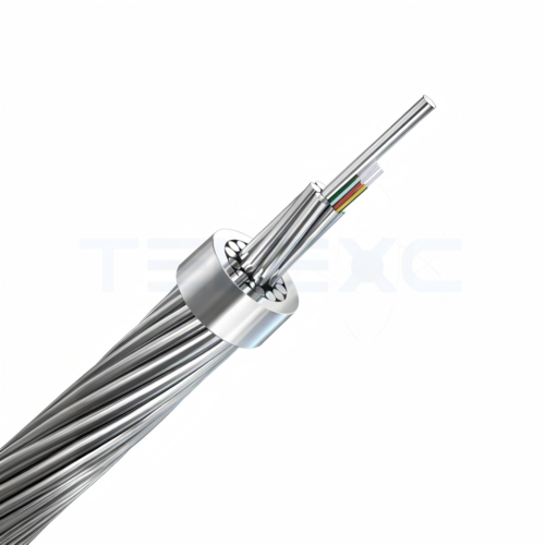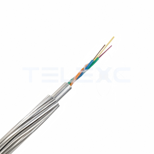
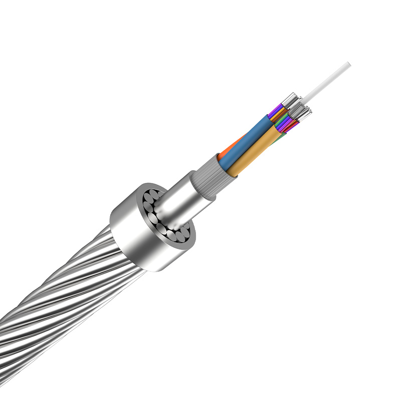

Aluminum PBT Tube OPGW Cable

  • Application: Ideal for aging grid retrofits & heavily polluted zones.

  • Anti-Corrosion: Engineered for high salt-spray & chemical environments.

  • Electrical Capacity: High short-circuit tolerance with low thermal impact.

  • Fiber Safety: Optimized shunting performance to protect internal fibers.

https://telexc.com/contact/

PBT Aluminum Tube Optical Ground Wire (OPGW) Cable is a specialized, dual-function cable engineered for overhead power transmission lines. It simultaneously serves two critical purposes:

  • Electrical Grounding: Provides reliable system grounding and lightning protection.

  • High-Speed Data Telecommunications: Facilities robust fiber-optic communication across the power grid infrastructure.

Structural Composition
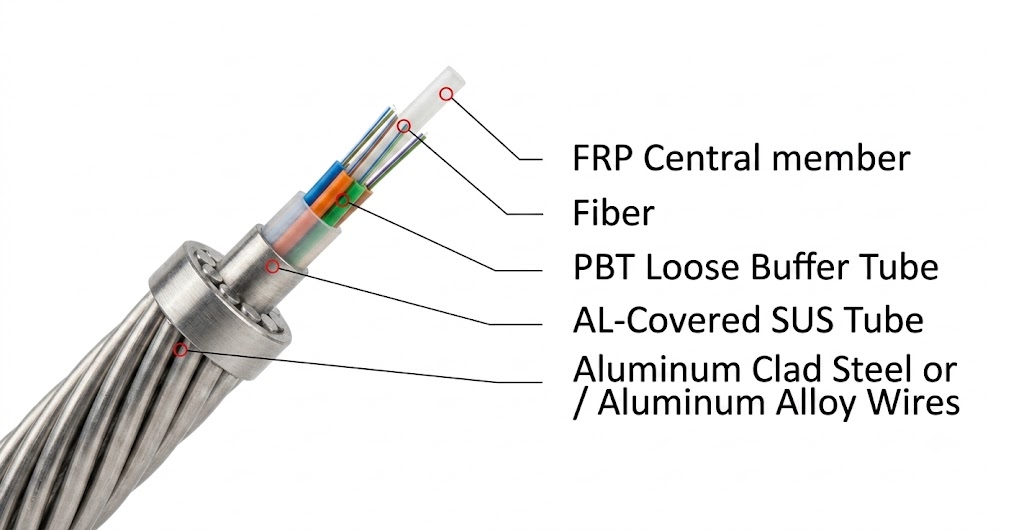
  • PBT Inner Tube: The core features a Polybutylene Terephthalate (PBT) tube to house the optical fibers. We select PBT for its superior mechanical strength, thermal stability, and excellent resistance to moisture and UV radiation.
  • Aluminum Cladding: A protective aluminum layer encases the PBT tube. This design enhances electrical conductivity, optimizes grounding efficiency, minimizes electromagnetic interference (EMI), and provides excellent corrosion resistance.
  • Optical Fibers & Buffer Tubes: Multiple silica-based optical fibers sit inside buffer tubes. This structure isolates them from mechanical stress, attenuation, and physical wear.
  • Water-Blocking Compound: A specialized filling compound fills the interstices within the tube. It prevents moisture ingress and ensures long-term cable integrity.


What is PBT Loose Tube?

Polybutylene Terephthalate (PBT) is a premier engineering polymer for harsh environments. It features exceptional tensile strength, outstanding dimensional stability, and minimal moisture absorption. It maintains its physical properties even under high temperatures and high humidity.

In our OPGW cables, we place the optical fibers “loosely” inside this robust PBT tube and cushion them with a moisture-proof thixotropic gel. This advanced design isolates the delicate fibers from external mechanical loads, thermal expansion, and water ingress. It ensures long-term, stress-free fiber protection and reliable signal transmission on high-voltage lines.
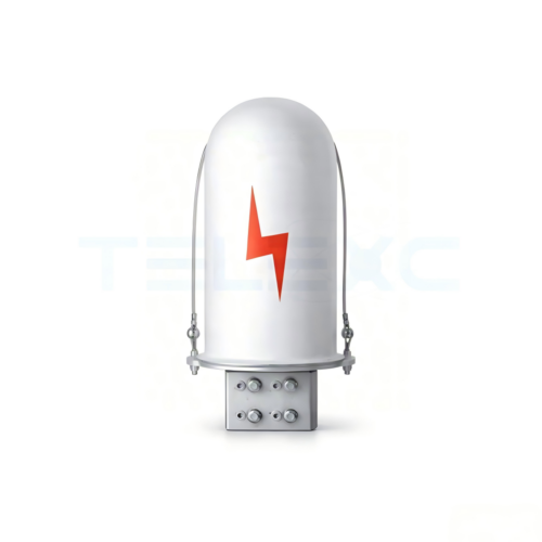
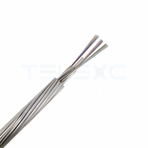
 

Specification Structure Maximum fiber count Supporting Cross Section(mm²) Diameter(mm) Weight (kg/km) DC Resistance(Ω/km) RTS(KN) Short Time Current Capacity l²t(KA²s)
OPGW-24B1-21/54[54;50]-PBT-4/1.6 12/2.4/20AS+AL-Tube7.2/5.0 24 75 12 385 0.58 54 55
OPGW-24B1-21/64[62;55]-PBT-2/2.4 13/2.5/20AS+AL-Tube8.1/6.2 24 85 13.1 455 0.3 62 55
OPGW-24B1-21/64[74;51]-PBT-4/2.0 13/2.5/27AS+AL-Tube8.1/6.2 24 85 13.1 507 0.568 74 51
OPGW-24B1-18/78[94;65]-PBT-4/2.0 10/3.15/20AS+AL-Tube7.2/5.4 24 96 13.5 592 0.651 94 65.4
OPGW-24B1-28/71[70;72]-PBT-3/2.3 9/2.45/20AS+6/2.45AA+AL-Tube9.0/6.7 36 99 13.9 482 0.42 70 72
OPGW-36B1-29/71[82;70]-PBT-3/2.0 7/2.75/27AS+5/2.75/20AS+AL-Tube7.9/5.1 36 100 13.4 540 0.57 82 70
OPGW-36B1-29/71[90;68]-PBT-3/2.0 12/2.75/20AS+AL-Tube7.9/5.1 36 100 13.4 580 0.538 90 68
OPGW-24B1-28/80[85;84]-PBT-3/2.3 13/2.8/27AS+AL-Tube9/6.7 36 108 14.6 580 0.46 88 84
OPGW-4/PT-48B1-26/96[111.6;138] 9/3.2/20AS+3/3.2AA+AL-Tube9.6/7.7 24 122 16 652 0.41 111.6 138
OPGW-36B1-16/129[85;50]-PBT-4/1.6 10/2.52/20AS+16/2.52AA+AL-Tube5.8/3.7 36 145 15.88 622 0.282 85 170
OPGW-48B1-55/98[111.6;151]-PBT-4/2.3 8/3.1/27AS+5/3.1/20AS+AL-Tube10.2/5.8 48 153 16.4 775 0.33 111.6 151
OPGW-36B1-55/105[125;144]-PBT-4/2.3 10/3.2/20AS+3/3.2/40AS+AL-Tube10.8/6.8 36 160 17.2 822 0.29 125 144
                 
OPGW-36B1-55/105[125;144]-PBT-4/2.3
OPGW : Optical Fiber Composite Overhead Ground Wire
36B1 : Fiber Count & Type ,Contains 36 fibers of G.652 single-mode fiber standard (typically G.652D).
55 :(Calculated Cross-Sectional Area): Represents the conductive metal cross-sectional area or the equivalent cross-section (approximately 55mm^2), used for fault current sizing calculations.
[125;144] (Mechanical & Electrical Limits): * 125 (RTS): Rated Tensile Strength of 125KN
*144 ( I ² * t): Short-Circuit Thermal Capacity of 144kA²·s

10/3.2/20AS+3/3.2/40AS+AL-Tube10.8/6.810/3.2/20AS:10 strands of 3.7mm Aluminum-Clad Steel wires (27% IACS conductivity)
3/3.2/40AS:3 strands of 3.2mm Aluminum-Clad Steel wires (40% IACS high conductivity)
AL-Tube10.8/6.8:Core Tube:Aluminum Tube (Outer Diameter: 10.8mm / Inner Diameter: 6.8mm)

Applications

  • Grid Modernization & Retrofitting: Engineered for the upgrading and capacity expansion of aging power transmission lines and low-voltage (LV) distribution networks.

  • Severe Chemical & Saline Environments: Highly recommended for coastal chemical industrial zones, heavy industrial bases, and regions with extreme environmental pollution.

Key Technical Advantages

  • Dual Electrical & Corrosion Excellence: Optimized to deliver exceptional electrical conductivity while maintaining superior long-term resistance to heavy chemical, atmospheric, and high-salinity coastal environments (compliant with IEEE guidelines).
  • Advanced Lightning & Mechanical Resilience: Features an optimized AA/ACS wire configuration. In critical applications, aluminum alloy (AA) wires can be fully replaced with heavy-duty aluminum-clad steel (ACS) to maximize structural tensile strength and lightning strike resistance.
  • Enhanced Electrical Capacity: The central aluminum core tube significantly expands the conductor’s cross-sectional area, drastically improving overall short-circuit current capacity and shunting efficiency.
  • Maximum Fiber Protection: Provides robust thermo-mechanical shielding to internal optical fibers, ensuring zero degradation from destructive thermal or mechanical stresses during severe grid fault events.

FAQs

Q1: Why choose a PBT loose tube design over a stainless steel tube for OPGW cables?

A: PBT (Polybutylene Terephthalate) buffer tubes provide exceptional flexibility, excellent resistance to moisture/UV radiation, and outstanding chemical stability. When combined with a protective aluminum cladding, the PBT inner tube ensures a more cost-effective yet highly durable structure. It delivers superior vibration dampening for the internal optical fibers, making it ideal for standard overhead transmission line upgrades, especially in medium-to-short span networks.

Q2: How does the aluminum cladding improve the cable’s performance during a short-circuit?

A: The robust outer aluminum cladding drastically increases the cable’s overall electrical conductivity and short-circuit current-carrying capacity. During a fault condition or lightning strike, the aluminum layer efficiently shunts the heavy current to the ground, minimizing heat buildup. This rapid thermal dissipation protects the internal PBT tube and the delicate optical fibers from structural and thermal degradation.

Q3: Is this PBT Aluminum Tube OPGW cable suitable for high-pollution coastal areas?

A: Yes. The external aluminum cladding forms a natural, dense oxide layer that provides excellent corrosion resistance against high salt-spray, humidity, and industrial chemical environments. For extreme coastal environments, we can further optimize the outer wire strands (such as using high-grade Aluminum Alloy Conductors – AAAC) to guarantee an extended service life.

Q4: What installation precautions should we take for this specific OPGW structure?

A: Like all aerial fiber infrastructure, you should install the cable using standard tension-stringing techniques to prevent over-bending or excessive mechanical stress. Ensure that the compatible tension clamps, suspension clamps, and down-lead clamps match the precise outer diameter and rated tensile strength (RTS) of the cable. We recommend maintaining the minimum bending radius during both stringing and final sagging operations to guarantee long-term OSP performance.

Key Parameters for Custom Design:
To ensure an accurate cable design and price calculation, please provide the following technical requirements with your inquiry:

  •  Power transmission line voltage level
  •  Required fiber count
  •  Preferred cable structure & maximum outer diameter
  •  Rated Tensile Strength (RTS)
  •  Short-circuit current capacity & fault duration

Testing & Quality Control

1. Type Test
The type test may be waived by submitting the manufacturer’s certificate for a similar product, performed by an internationally acknowledged, independent testing organization or laboratory. If a specific type test is required, it will be carried out according to an supplementary type test procedure mutually agreed upon by the purchaser and the manufacturer.

2. Routine Test
The optical attenuation coefficient on all production cable lengths is strictly measured in accordance with IEC 60793-1.

Standard Single-Mode Fibers (G.652D): Measured at both 1310 nm and 1550 nm.

Non-Zero Dispersion-Shifted Fibers (G.655 / NZDS): Measured at 1550 nm using the optical time-domain reflectometer (OTDR) backscattering technique.

3. Factory Acceptance Test (FAT)
The Factory Acceptance Test is carried out on two samples per order, either in the presence of the customer or their authorized representative. The specific quality characteristics and inspection criteria are determined by relevant international standards and agreed quality plans.