
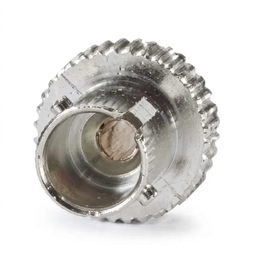
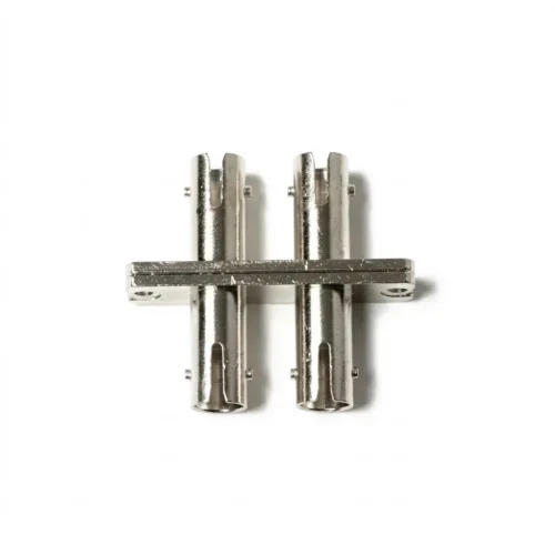
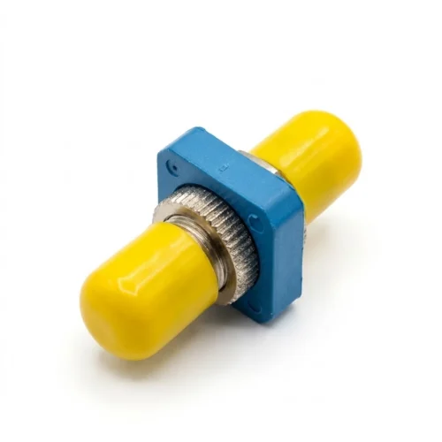
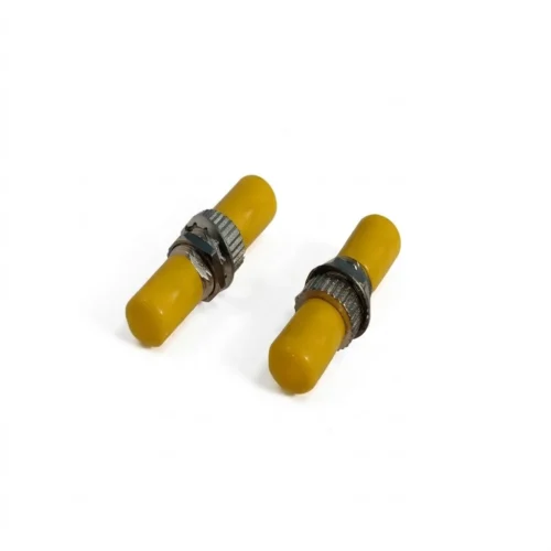
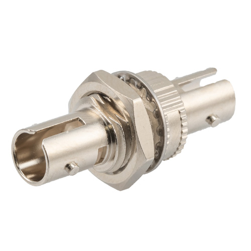
The ST universal fiber optic coupler is a passive fiber optic connection component design to join or connect compatible fiber optic connectors. It enables optical signals to pass between fiber optic cables and network equipment with minimal signal loss. The ST fiber optic couplers provide a secure and aligned connection between fiber optic connectors to maintain reliable optical signal transmission. The coupler also contains a precision alignment sleeve that holds the ferrules of two compatible ST connectors in the correct position. The connection process involves connector insertion, mechanical alignment, connector locking, and optical signal transmission. ST couplers provide connection points within these systems where ST-terminated equipment is installed. The couplers serve in fiber optic patch panels, telecommunication equipment rooms, enterprise networks, and industrial communication networks. Manufacturers and utility operations should ensure quality assurance to prevent excessive insertion loss, unstable connections, signal reflections, or intermittent communication.
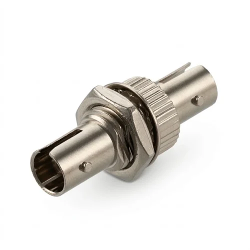
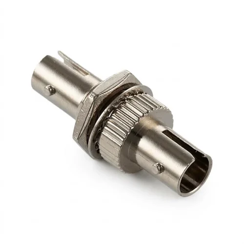
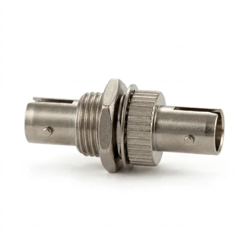
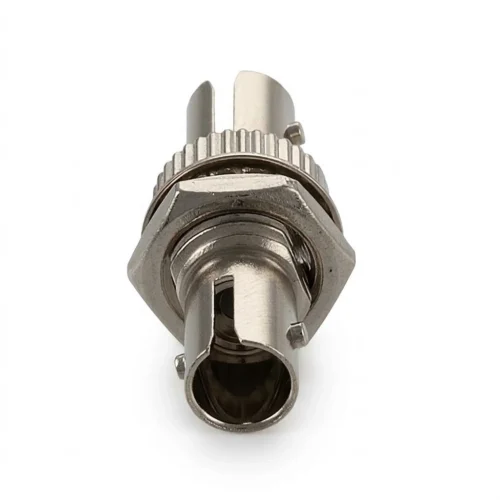
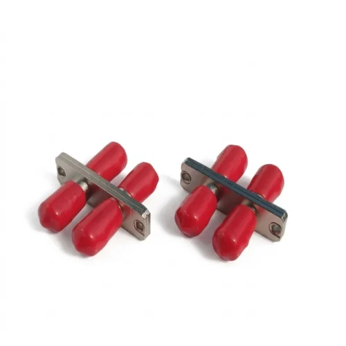
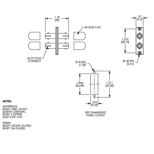
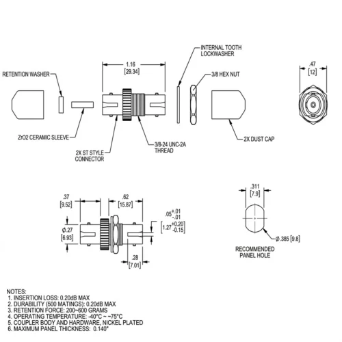
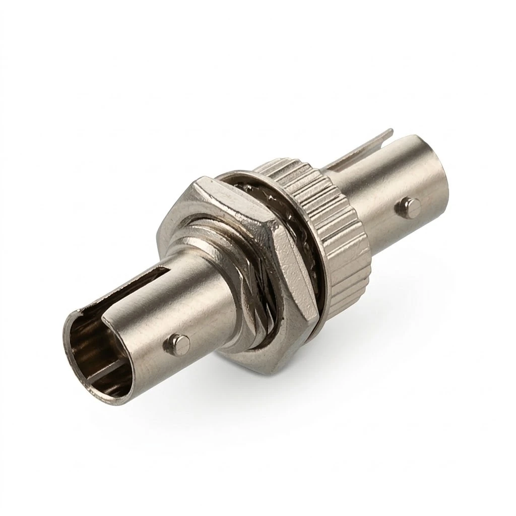
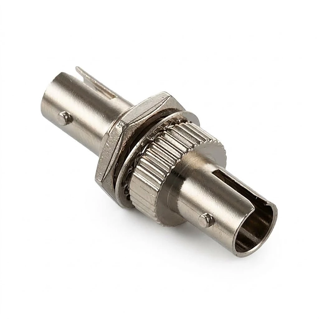
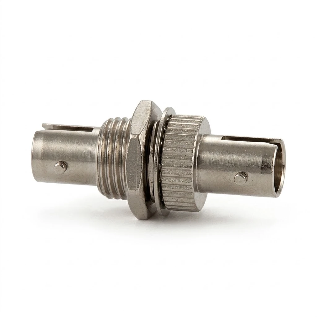
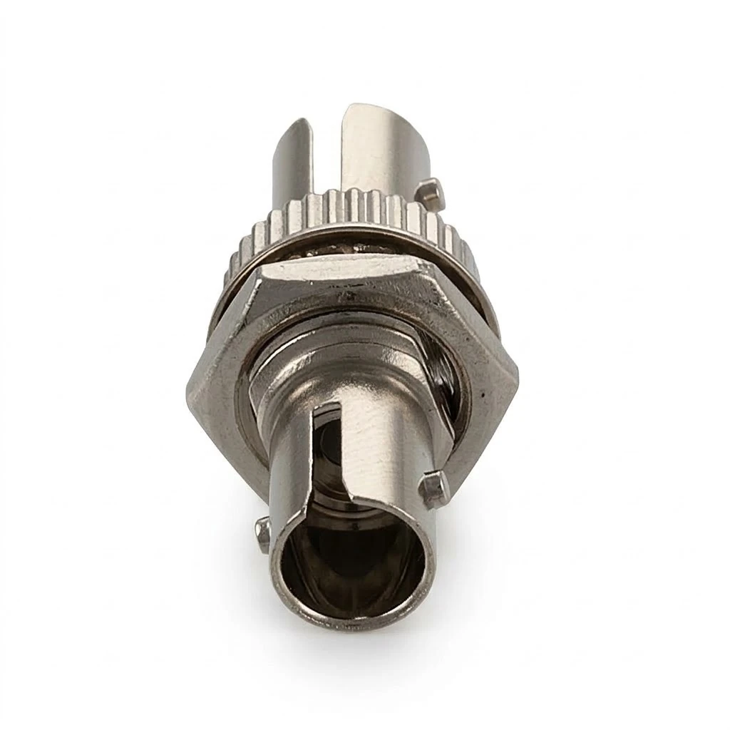
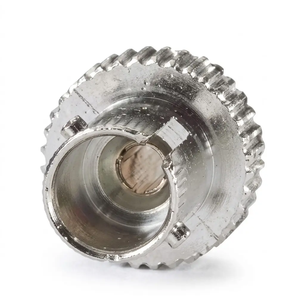
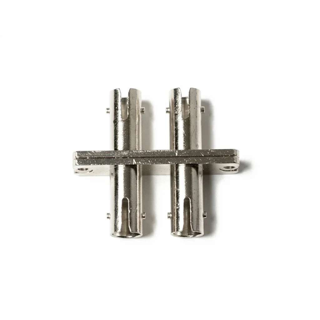
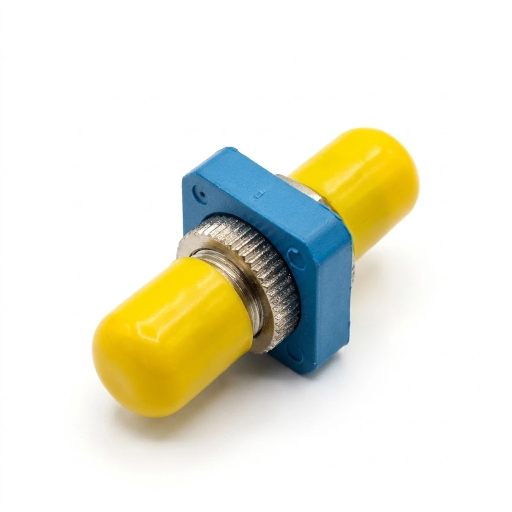
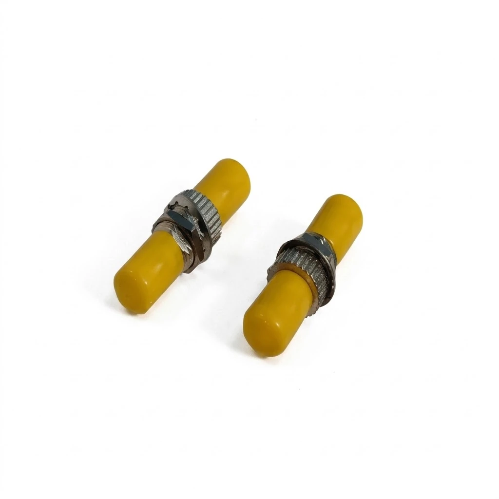
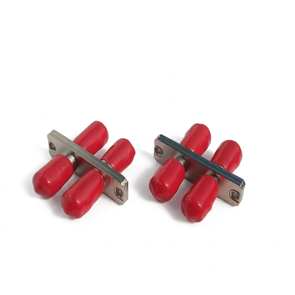
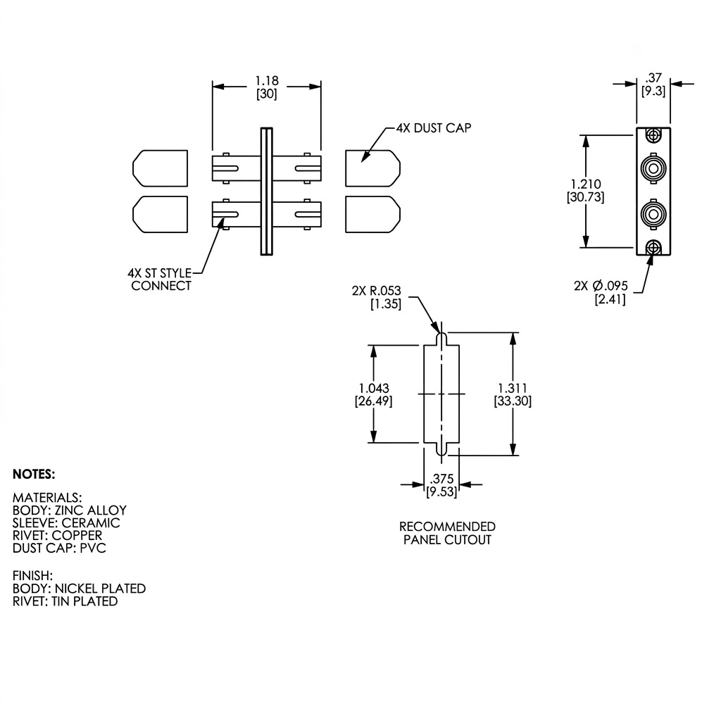
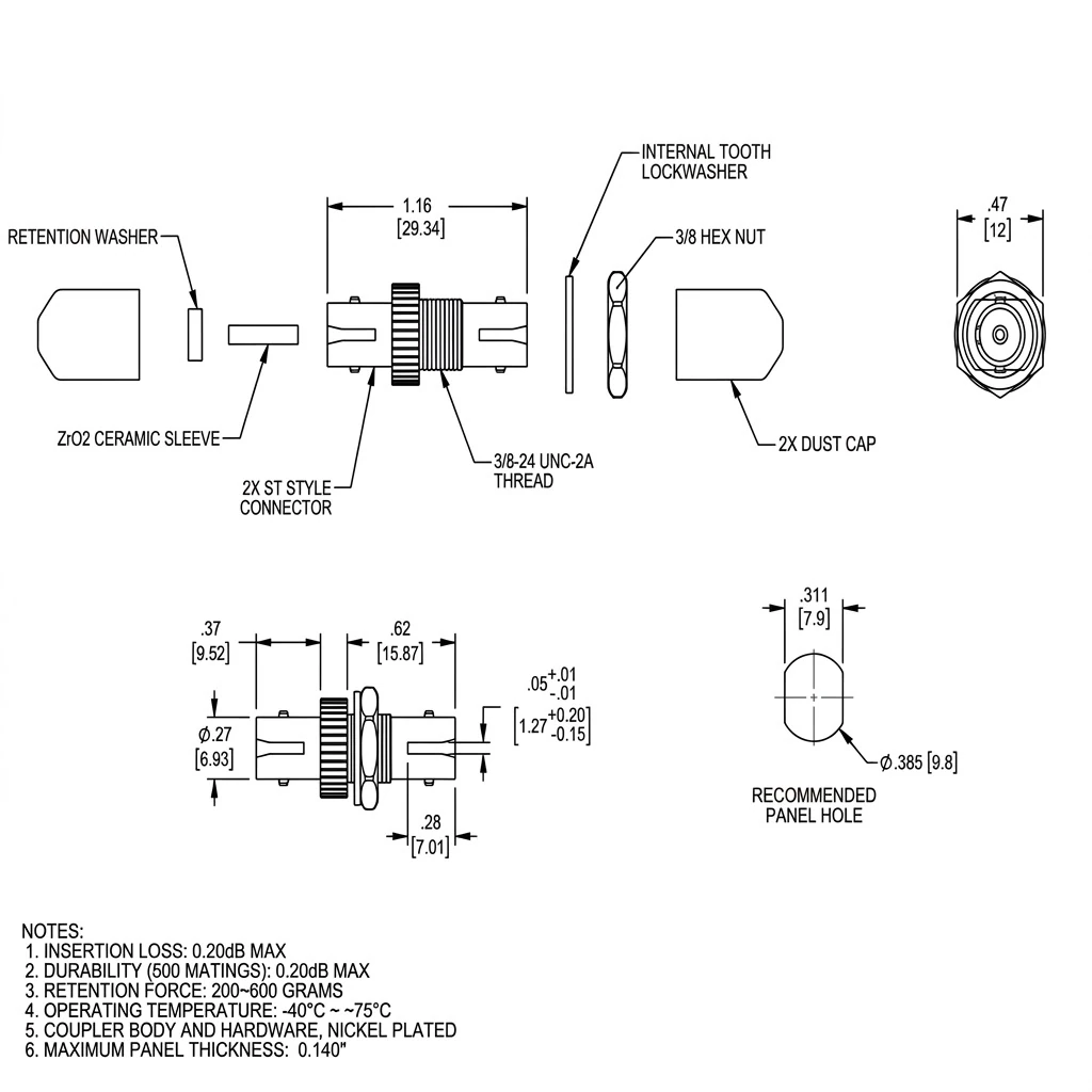
ST Universal Fiber Optic Coupler
ST Universal Fiber Optic Coupler
-
Metal Housing: Delivers mechanical protection for the mating sleeve and shields the optical connection in high EMI/RFI environments.
-
Ceramic Alignment Sleeve: Features a zirconia (ZrO2) ceramic sleeve for high-precision core alignment, supporting low optical attenuation across singlemode and multimode links.
-
Dual Alignment Sleeve Options: Available with ceramic or bronze alignment sleeves to match singlemode tolerances or rugged deployment requirements.
-
Low Insertion Loss: Delivers typical insertion loss of <= 0.15 dB and maximum insertion loss of <= 0.2 dB to protect link loss budgets.
-
Connector Compatibility: Accepts standard ST fiber optic connectors with physical contact (PC) or ultra physical contact (UPC) endfaces.
-
Dust Protection: Comes equipped with dust caps on both mating ports to guard against airborne dust and ferrule contamination before patching.

Structure and components of the ST universal fiber optic coupler
The structure of ST universal fiber optic couplers affects optical alignment, connection stability, signal transmission efficiency, and network reliability. The ST universal fiber optic coupler connects a passive fiber optic adapter that is designed to link connects a passive fiber optic adapter designed to connect two compatible ST fiber optic connectors. The structure and components include:
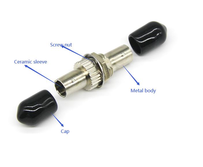
- Outer housing and protective body—this is the main structure that holds the internal alignment components in position. The body protects internal alignment sleeves from mechanical damage and provides resistance to ordinary handling stresses during installation and maintenance.
- Internal alignment sleeve—the sleeve positions the ferrules of two mating ST connectors along the same optical axis. Correct alignment reduces lateral displacement between the fiber cores and helps reduce optical insertion loss. The sleeve maintains concentric alignment between mating connector ferrules and supports repeatable optical connections during connector mating and unmating.
- ST connector interface—the interface receives compatible ST connectors on both sides of the coupler. It must maintain the correct geometry to ensure secure mating and proper alignment of the connector ferrules.
- Bayonet locking mechanism—this mechanism allows an ST connector to lock the coupler through a push-and-twist action. The design helps retain the connector during normal operation while allowing technicians to disconnect it when maintenance is needed.
- Mounting the flange and fixing the structure—this secures the coupler to a patch panel, optical distribution frame, termination box, or telecommunication enclosure. The mounting structure provides accurate panel alignment, secure retention during connector insertion, compatibility with the specified panel cutout, and mechanical strength to prevent movement.
- Internal retention and supporting components—an ST universal coupler may contain internal retaining features, sleeves, or supporting elements that hold the alignment sleeve in its correct position. The components help prevent movement that could compromise connector alignment.
Types of ST universal fiber optic closures
ST fiber optic closures join two compatible ST (straight tip) fiber optic connectors in telecommunications infrastructure. They provide mechanical alignment between connector ferrules and help maintain optical continuity between fiber optic cables, patch cords, and network equipment. Operators should consider fiber mode, alignment sleeve material, mounting configuration, connector compatibility, optical performance, and installation environment when selecting the ST closures.
ST simplex fiber optic couplers
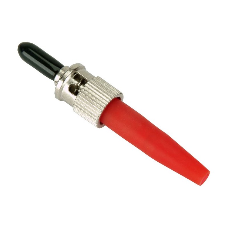
ST simplex couplers provide a single connection port on each side and allow two compatible ST connectors to be joined through one optical channel. They are installed in fiber optic patch panels. Distribution boxes, equipment racks, and industrial communication cabinets. These couplers are ideal for legacy enterprise networks, industrial communication systems, test equipment, and utility substations that use ST-terminated fiber optic connections.
ST duplex universal couplers
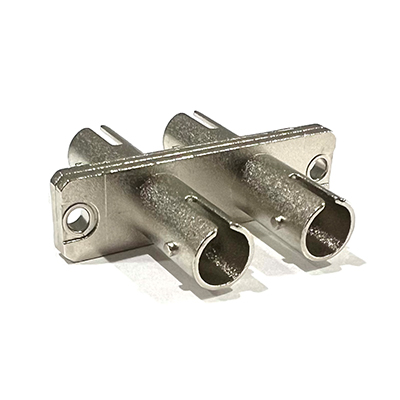
ST duplex couplers accommodate two optical channels within a shared assembly or mounting arrangement. These couplers have two optical channels in a combined assembly, consolidated mounting, and compatibility dependent on the specific panel, connector arrangement, and product design. These couplers serve where it can support equipment that needs two optical paths.
Ceramic-sleeve ST fiber optic couplers
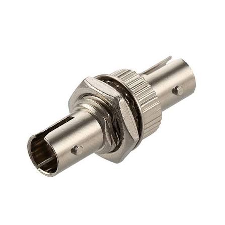
These couplers use a precision ceramic alignment sleeve made of zirconia to position mating connector ferrules accurately. The sleeve’s dimensional consistency and surface quality influence connector alignment and repeatability. These couplers offer high dimensional stability, good wear resistance, precise ferrule alignment, and insertion-loss performance when manufactured and assembled correctly. Ceramic-sleeve ST fiber optic couplers serve in telecommunication equipment rooms, fiber distribution panels, and other installations needing reliable optical connections.
Metal-housed ST universal coupler
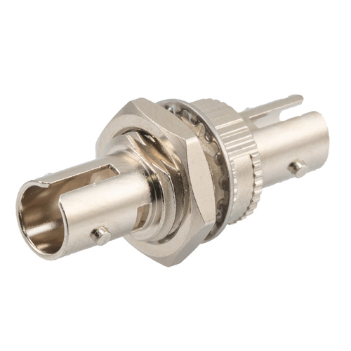
Metal housing ST couplers has a metallic outer body designed to provide mechanical support and withstand normal handling during installation and maintenance. The housing may consist of nickel-plated brass, stainless steel, or other metals. These offer mechanical rigidity, resistance to deformation, suitability for equipment panels, and corrosion resistance. Metal-housed ST couplers are ideal for industrial communication cabinets, utility control rooms, and substation equipment panels.
Single-mode ST couplers
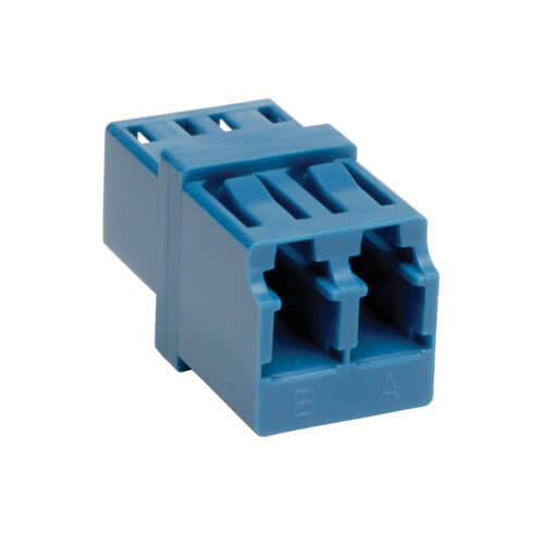
Single-mode ST couplers are ideal for compatible single-mode fiber systems where their performance depends on the alignment of the mating connector ferrules. They are designed for specified single-mode fiber applications and have suitable connector and fiber compatibility. The couplers serve in legacy single-mode telecommunications systems, optical test arrangements, and utility communication networks where ST interfaces remain in service.
Multimode ST fiber couplers
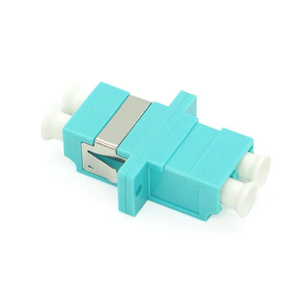
These are designed for compatible multimode fiber optic connectors. They work in legacy local-area networks, industrial communications, and data transmission installations. The couplers offer compatibility with specified multimode fiber systems, alignment requirements suitable to the connector design, and availability with different alignment sleeve and housing materials. They can connect fiber patch cords in industrial control networks, older enterprise installations, and selected utility communication systems.
The working principle of the ST fiber optic couplers
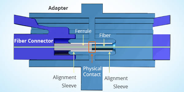
ST fiber optic couplers operate by aligning two compatible SE fiber optic connectors to enable optical signals to pass between their fiber cores. They do not generate, amplify, or convert optical signals. The two compatible ST connectors are inserted into opposite ends of the coupler. An internal precision alignment sleeve positions the connector ferrules along the same optical axis and reduces misalignment between the fiber cores. The bayonet-style twist-lock mechanism secures the connectors and maintains a stable physical connection. Light passes from one fiber end to the other through the aligned interface and enables data transmission across telecommunications and power utility communication networks. Proper alignment and secure connector retention help reduce insertion loss, maintain signal continuity, and improve communication reliability. The actual performance of the ST couplers depends on connector cleanliness, fiber compatibility, end-face condition, and coupler manufacturing quality.
How utility operators and planners select the right ST universal fiber optic couplers
Utility operators and telecommunications planners select ST universal fiber optic couplers based on optical performance, connector compatibility, installation needs, and environmental conditions. The components connect compatible ST fiber optic connectors in communication systems used for substation automation, SCADA networks, industrial control, and telecommunications infrastructure. Selecting the right coupler reduces optical signal loss, maintains stable connections, and reduces the risk of communication failures. Here are the key factors to consider when selecting the couplers.
- Assess connector and fiber compatibility—verify that the coupler matches the connectors and fiber optic cables used in the existing network. Planners should evaluate connector type, fiber mode, ferrule dimensions, and connector polish.
- Evaluate optical performance—operators should check insertion loss and return loss. Manufacturers should also provide test data showing that the coupler meets the specified performance requirements.
- Select the suitable alignment sleeve—this sleeve positions the ferrules of mating ST connectors to maintain optical alignment. Its material and manufacturing tolerances influence connection consistency and durability. Common options include ceramic sleeves and metal sleeves.
- Consider housing material and mechanical strength—the coupler housing protects the internal alignment components and provides structural support during installation and maintenance. The selected housing should withstand expected handling, vibration, and operating conditions without compromising connector alignment.
- Determine the required mounting configuration—the design must fit the existing fiber distribution system. Operators should verify whether the coupler is ideal for a patch panel, optical distribution frame, termination box, and equipment enclosure.
Technical specifications for ST fiber optic couplers
| Product type | ST mating adapter/coupler |
| Connector type | ST |
| Body type | Simplex |
| Fiber compatibility | Universal single-mode and multimode |
| Polish compatibility | PC, UPC |
| Testing wavelength | 1310 nm, 1550 nm (Single Mode); 850 nm, 1300 nm (Multimode) |
| Insertion loss | Typical <= 0.15 dB, Max <= 0.2 dB |
| Repeatability | <= 0.10 dB |
| Exchangeability | <= 0.20 dB |
| Durability | 1000 mating cycles, max <= 0.20 dB |
| Housing material | Metal |
| Alignment sleeve | Ceramic (ZrO₂) or customized (bronze option supported) |
| Mounting profile | Flanged; fits 3/8 inch D-hole cutouts and standard rectangular cutouts |
| Operating temperature | -40 °C to +75 °C (-40 °F to +167 °F) |
| Storage temperature | -40 °C to +75 °C (-40 °F to +167 °F) |
Applications of ST universal fiber optic couplers
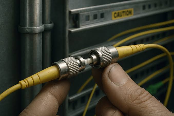
- FTTx deployments—optical distribution frames, fiber distribution hubs, and outdoor terminal boxes.
- Local area networks—equipment room distribution fields, cross-connect frames, and backbone patching.
- High EMI/RFI environments—industrial manufacturing plants, electric control rooms, and substations where metallic shielding is required.
- Security & surveillance systems—video monitoring networks and perimeter defense infrastructure using bayonet-locking ST cabling.