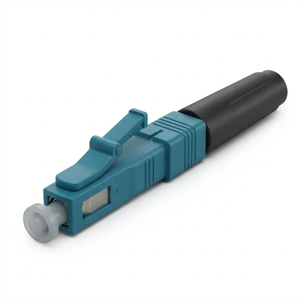

Fiber Fast Connector LC APC Field Assembly Connector
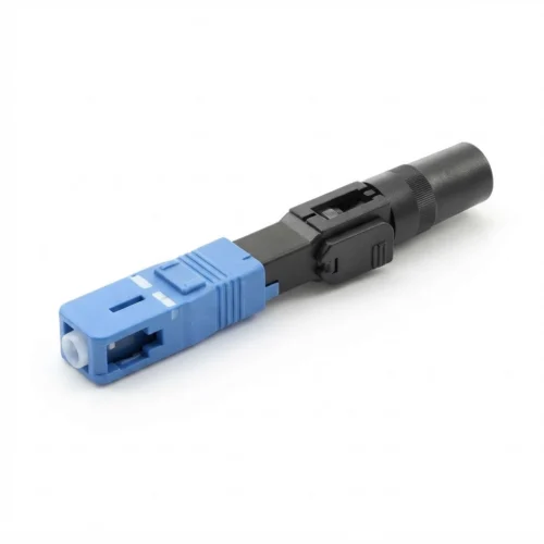
The LC APC Fiber Optic Quick Connector provides a field-installable optical termination designed for single-mode networks. Equipped with a factory-polished ceramic ferrule and an internal mechanical splice stub, this connector enables rapid terminations without epoxy, curing ovens, or fusion splicing equipment. It serves emergency restoration workflows, FTTH drop cable drops, and high-density distribution patch panels where fast turn-up is critical.
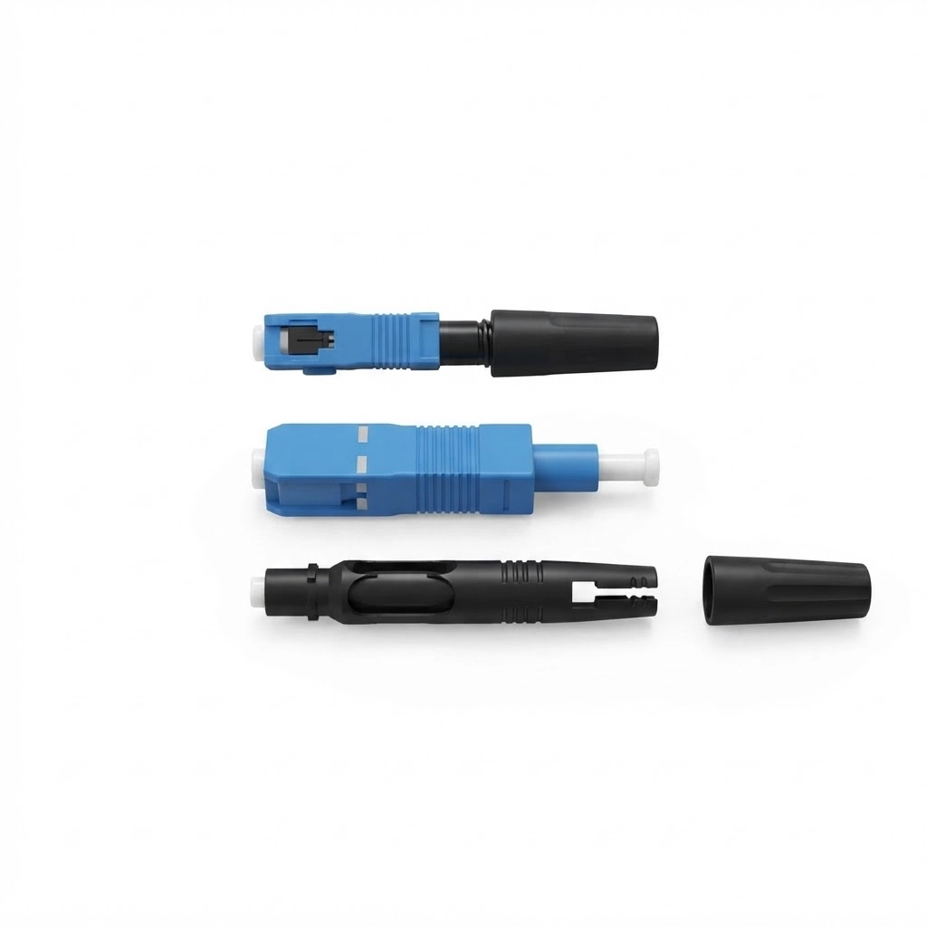
Product Configuration
-
Connector Type: LC
-
Polish Type: APC (Angled Physical Contact, 8-degree angle)
-
Housing Color: Green
-
Configuration: Simplex
-
Ferrule Material: Zirconia ceramic
-
Fiber Mode: Single-mode 9/125 um (compatible with ITU-T G.657.A1)
-
Cable Compatibility: 250 um bare fiber, 0.9 mm tight-buffered fiber, 2.0 mm jacketed cable, and 2.0 x 3.0 mm butterfly flat drop cable
-
Boot Options: 250 um, 0.9 mm, and 2.0 mm configurations
Technical Specifications
-
Insertion Loss: <= 0.3 dB [Needs manual confirmation: Source contains conflicting vendor notation of >= 0.3 dB vs <= 0.3 dB]
-
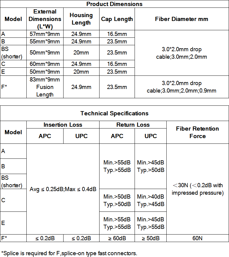
Return Loss: > 50 dB for APC polish (source also notes alternate vendor rating of <= 55 dB; UPC variants rated > 40 dB)
-
Assembly Time: <= 2 minutes
-
Mating Durability: >= 500 mating cycles
-
Operating Temperature: -40 deg C to 85 deg C
-
Dimensions: 51 x 9 x 7 mm (approx. 2.0 x 0.35 x 0.28 inches; assembled height 0.28 inches)
Applications
-
Fiber-to-the-Home (FTTH) drop cable terminations at customer premises
-
Optical Distribution Networks (ODN) and Fiber Distribution Hubs (FDH)
-
CATV distribution networks requiring high return loss to suppress analog back-reflection
-
Telecommunications access networks and enterprise structured cabling
-
Emergency fiber link restoration and field repairs where electric power is unavailable
-
Test benches and temporary optical measurement connections
Installation and Deployment Guidelines
-
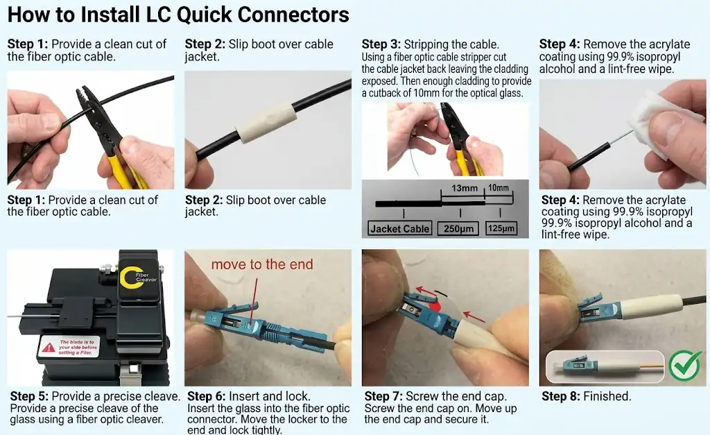
Cable Preparation: Thread the fiber through the rear boot. Strip the outer cable jacket and trim internal reinforcing strength members to the required exposure length.
-
Buffer Stripping: Strip the 250 um acrylate coating from the bare glass using a calibrated mechanical fiber stripper.
-
Fiber Cleaning: Clean the bare glass fiber using lint-free optical wipes saturated with isopropyl alcohol.
-
Precision Cleaving: Cleave the bare fiber using a precision cleaver to maintain a stripped length between 9 mm and 10 mm.
-
Fiber Docking: Insert the prepared fiber slowly into the rear of the connector until it docks against the internal factory stub and exhibits a slight bend, confirming contact.
-
Mechanical Locking: Slide the switch casing upward to engage the internal V-groove clamp and secure the bare fiber.
-
Dust Cap Maintenance: Keep the protective dust cap installed until the connector mates with an adapter to prevent airborne contamination.
-
Shard Disposal: Collect all cleaved glass fiber waste immediately using adhesive tape to maintain safe work area conditions.
Engineering Selection Considerations
-
When This Product Is the Right Choice:
-
Field operations requiring quick manual termination without carrying fusion splicers, generators, or wet epoxy kits.
-
Rapid restoration jobs and FTTH subscriber drops using 2.0 x 3.0 mm butterfly drop cable or 0.9 mm buffered fiber.
-
Optical links requiring strict APC back-reflection control (> 50 dB return loss) for video or high-split passive optical networks.
-
Scenarios where field technicians require re-termination capability to correct cleave or insertion misalignments on site.
-
-
When This Product May Not Be Suitable:
-
Infrastructure where installation quality must be completely independent of operator technique; fusion splicing provides higher repeatability and lower long-term splice drift.
-
Direct outdoor environments lacking an external enclosure; this connector body is not environmentally sealed and must reside within a weatherproof terminal box or closure.
-
Networks with inexperienced field crews who cannot reliably handle and seat delicate 250 um bare fiber without damage.
-
-
Common Selection Mistakes to Avoid:
-
Mating green APC (angled) connectors with blue UPC (straight physical contact) connectors, which damages ferrule end-faces and generates excessive insertion loss.
-
Interchanging boot parts between 250 um, 0.9 mm, and 2.0 mm cables, resulting in loose clamping and compromised tensile retention.
-
Deviating from the 9 mm to 10 mm cleave length tolerance, leading to internal fiber buckling or air gaps.
-
Frequently Asked Questions (FAQ)
-
What is the functional difference between LC/APC and LC/UPC fast connectors? LC/APC connectors feature an 8-degree angled ceramic ferrule end-face (green housing) that reflects light into the cladding, providing return loss > 50 dB. LC/UPC connectors feature a flat radiused end-face (blue housing) with return loss typically > 40 dB. LC/APC is required for CATV and reflection-sensitive FTTH access networks.
Which fiber and cable types can this connector terminate?
The connector terminates single-mode 9/125 um G.657.A1 optical fiber. It accommodates 250 um bare fiber, 0.9 mm tight-buffered fiber, 2.0 mm jacketed cordage, and 2.0 x 3.0 mm flat butterfly drop cable when using the matching boot configuration.
Is a fusion splicer or curing oven needed for installation?
No. The unit uses a mechanical V-groove splice with index-matching gel and an embedded factory-polished fiber stub, eliminating fusion splicers, electrical power, epoxy adhesives, and field polishing films.
Can this connector be re-terminated if insertion loss is high?
Yes. The mechanical locking casing can be released, allowing technicians to withdraw the fiber, clean, re-cleave, and re-insert the glass against the internal stub.
What is the correct bare fiber strip length before cleaving?
The bare glass must be cleaved to leave 9 mm to 10 mm of bare fiber extending past the buffer coating to ensure accurate seating against the internal fiber stub.
How can a technician check optical continuity during field termination?
A Visual Fault Locator (VFL) can be connected to the LC ferrule during termination; minimal visible red light leakage through the connector body confirms proper fiber core alignment.
Conclusion
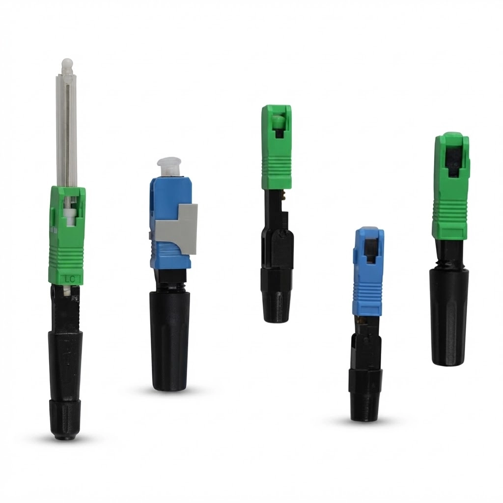
The LC APC Fiber Optic Quick Connector delivers an efficient mechanical termination method for FTTH drop cables and emergency restorations. By combining a factory-polished zirconia ceramic ferrule with a reusable V-groove clamp, this connector maintains dependable optical continuity without requiring specialized field termination machinery.