
Fiber Optic Splice Closure (FOSC)
Fiber Optic Splice Closure Engineering Guide
A fiber optic splice closure is a protective housing engineered to organize, store, and shield optical fiber splices and exposed cables from environmental damage. Used in outside plant (OSP) and indoor distribution links, this equipment preserves the continuity of optical signals by isolating sensitive fusion or mechanical splices from mechanical tension, water ingress, and thermal fluctuations.
… Load moreShowing 1–12 of 16 results
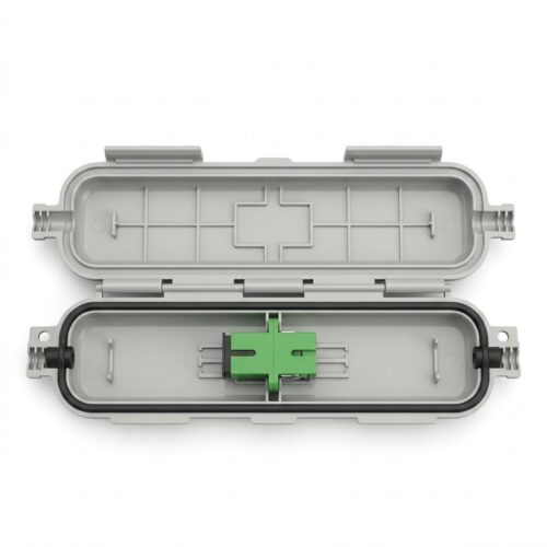
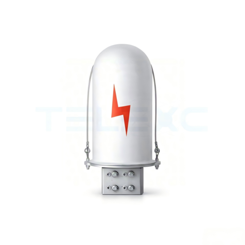
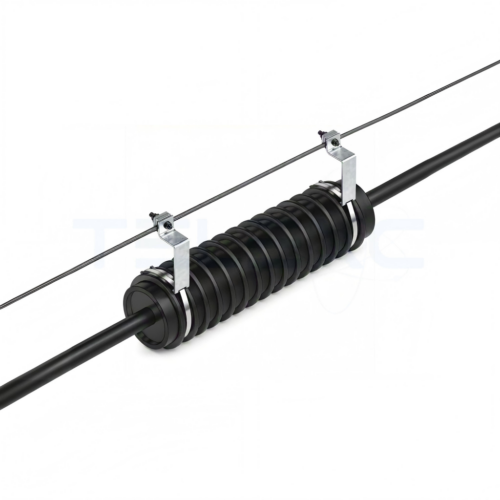
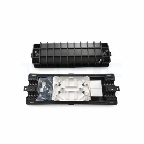
Deploying a reliable fiber optic splice closure ensures long-term operational integrity across trunk lines, feeder networks, distribution branches, and final drop segments within optical distribution networks (ODN).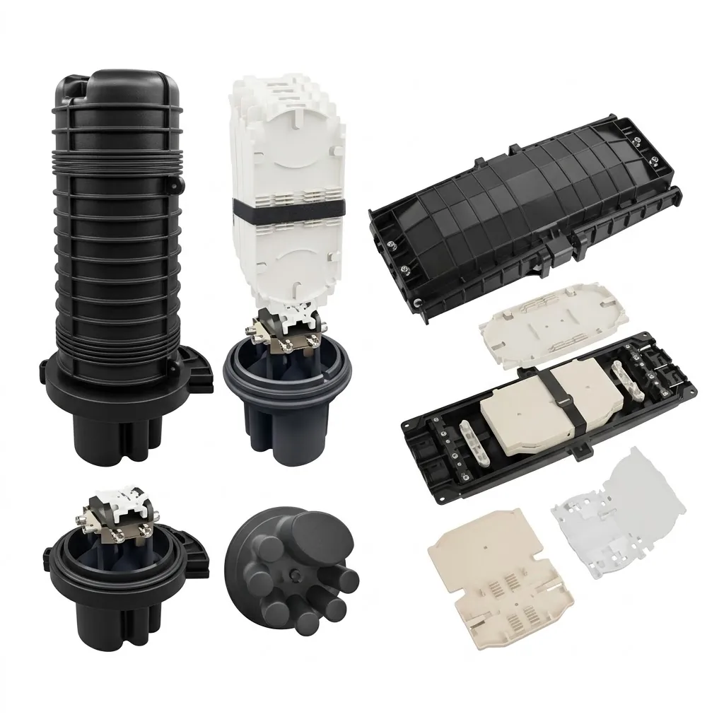
Structure and Internal Components
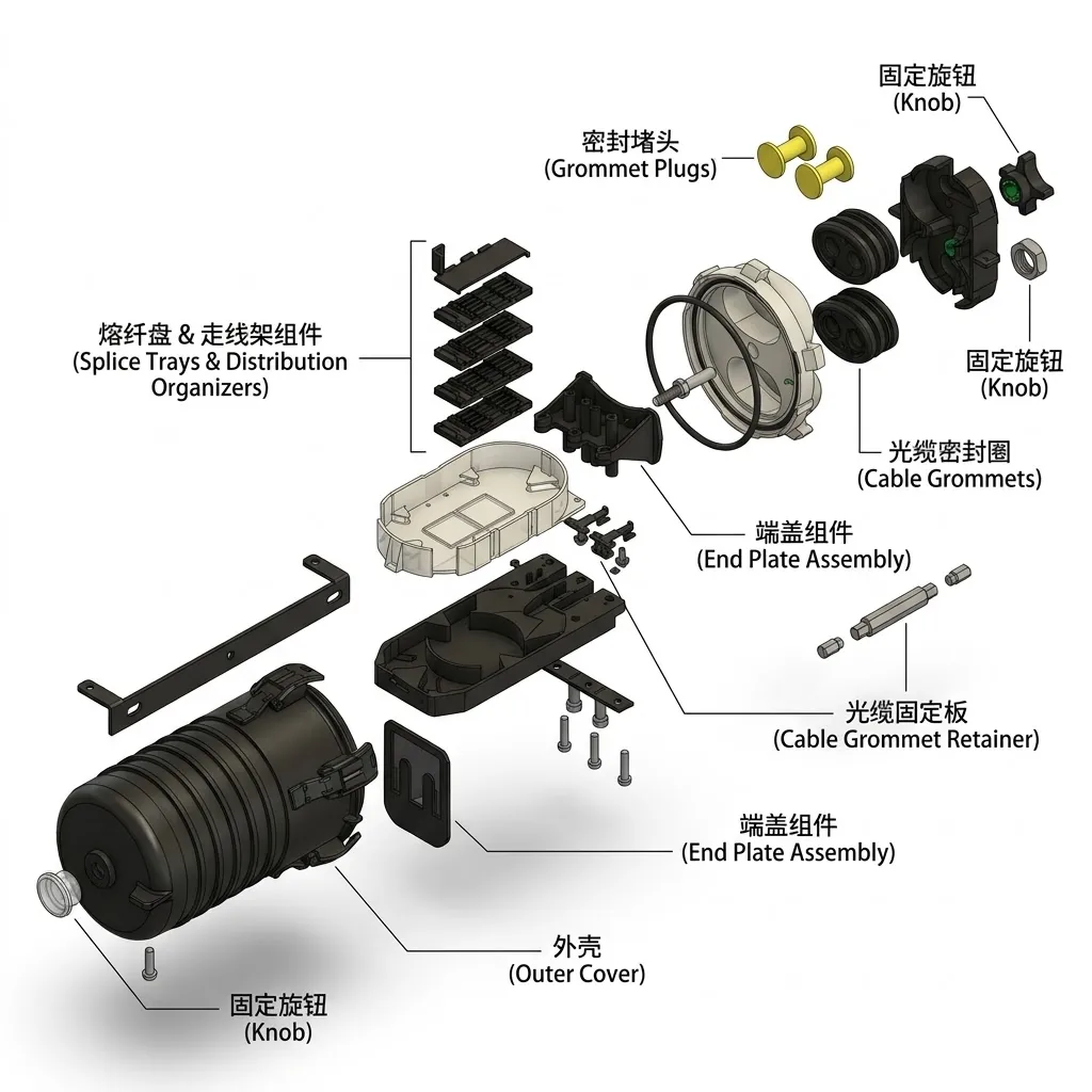
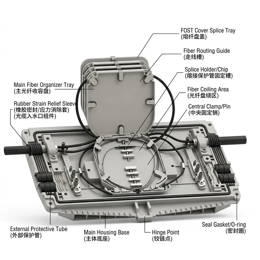
The structural integrity of an optical splice closure depends on several internal and external mechanical sub-assemblies:
-
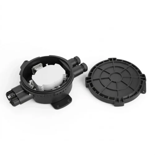
Outer Housing: Molded from high-tensile engineering plastics such as polycarbonate (PC) or modified polypropylene (PP), and occasionally metal for specific utility setups. The outer shell provides impact resistance, compression strength, flame retardancy, and protection against ultraviolet radiation, moisture, and dust.
-
Support Frame: The internal chassis that fastens to the housing, anchoring internal components and providing mechanical rigidity.
-
Cable Retention and Strength Member Clamp: Mechanical hardware designed to secure incoming cable sheaths and clamp central or peripheral strength members (metallic or dielectric). This mechanism transfers tensile loads away from fragile fibers and counteracts expansion or contraction caused by temperature swings.
-
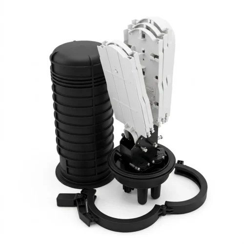
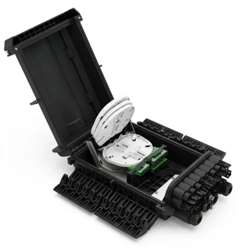
Splice Trays: Hinged, stackable organizers equipped with fiber management tracks. Standard tray configurations store spliced fibers and maintain controlled bend radii. Trays may accommodate 12 to 24 fibers per tray, stacking up to multi-layer formats (such as 4-tray assemblies handling 48 fibers, up to 144 fibers or more).
-
Splice Sleeve Holders: Grooved clips mounted within the splice tray designed to firmly seat heat-shrinkable protective sleeves or mechanical connectors.
-
Slack Storage Baskets: Dedicated routing zones designed to store excess buffer tubes, bare fiber slack, or uncut fibers in midspan access applications.
-
Sealing Interfaces: Cable entry port seals configured using either heat-shrink sleeves lined with hot-melt adhesive or mechanical elastomeric gaskets and O-rings.
Classifications: Horizontal vs. Vertical Closures
Splice closures are broadly categorized into two structural profiles based on mechanical design and cable port geometry:
Horizontal (In-Line) Closures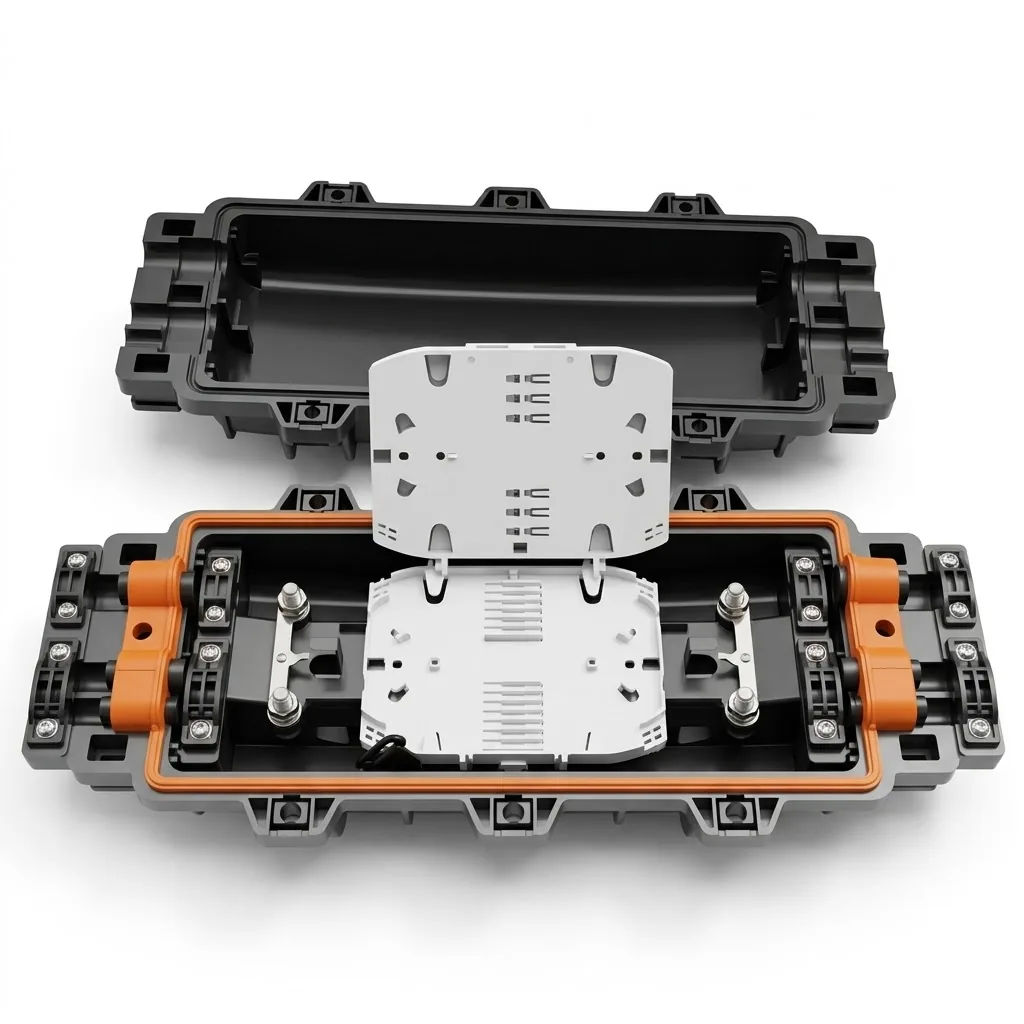
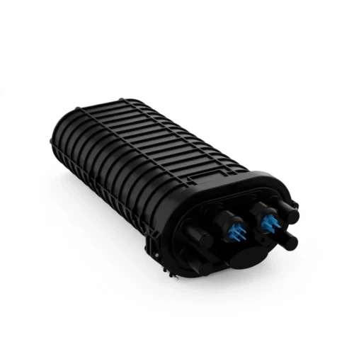
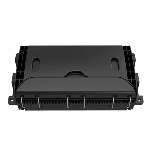
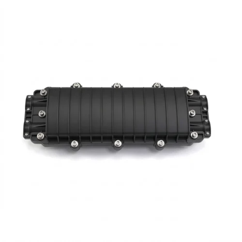
Horizontal closures feature a flat, rectangular, or cylindrical profile with cable entry ports positioned at opposing ends.
-
Port Arrangement: Opposing ends allow straight-through (in-line) routing, making them practical for joining identical cables or performing emergency line repairs.
-
Installation Environments: Suitable for aerial strand mounting, manholes, handholes, wall attachments, and direct-buried configurations.
-
Operational Ratings: Typical designs operate across temperatures ranging from -40 deg C to 85 deg C, withstand internal pressure variations of 70 to 106 kPa, and accommodate up to 144 fibers.
-
Application Scope: Common in long-haul concatenation, pipeline laying, and trunk cable repair.
Vertical (Dome) Closures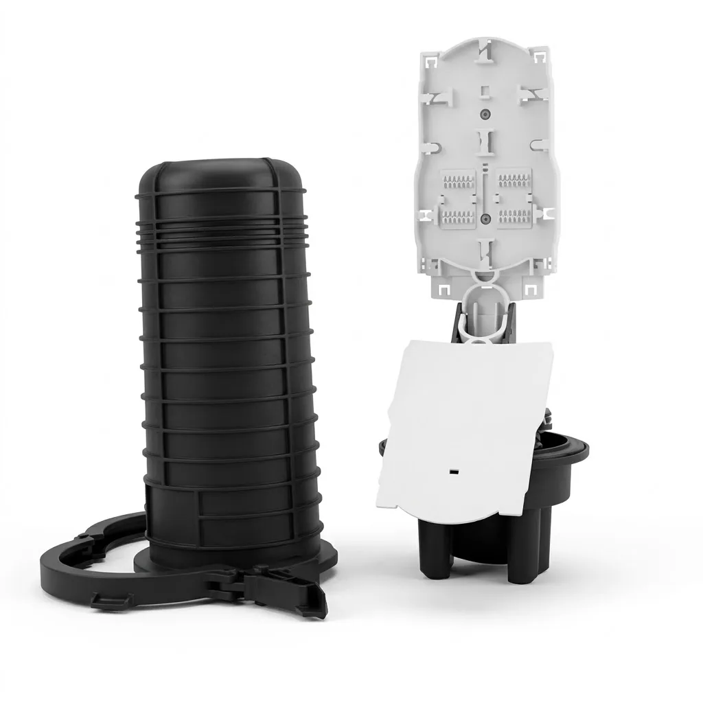
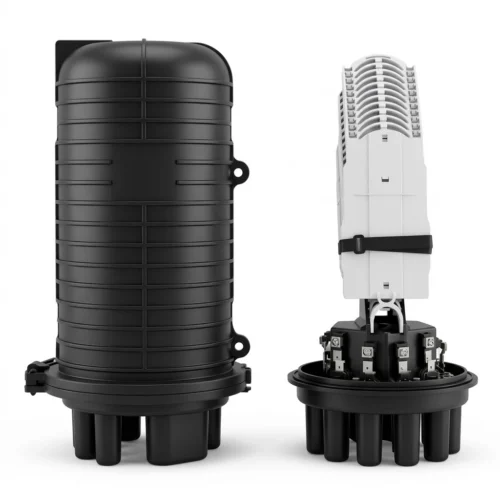
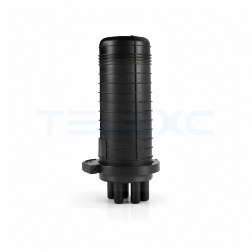
Vertical closures, commonly referred to as dome closures or butt-style closures, have a cylindrical dome-and-base construction where all cable access ports are grouped at a single end.
-
Port Arrangement: A single base incorporates multiple round branch ports and typically one oval port designed for midspan loop-through cabling.
-
Installation Environments: Suited for underground vaults, handholes, direct-buried pits, pole mounts, and pedestal integration.
-
Re-entry Characteristics: The single-clamp base-to-dome seal facilitates repetitive network re-entry for moves, adds, and changes (MACs) without disturbing existing drop connections.
-
Application Scope: Widely selected for FTTH distribution points, local aggregation nodes, and branching feeder architectures.
Working Principle
A fiber splice closure operates by isolating delicate silica glass fibers from mechanical and environmental stresses. When an outdoor cable enters the closure, the outer jacket and central strength members are anchored to the internal support chassis. This mechanical termination directs all axial tensile loads, bending moments, and torsional forces into the closure structure rather than into the optical fibers.
Within the interior, stripped buffer tubes transition cleanly onto splice trays. Bare fibers route through engineered guide channels that enforce minimum bending radii to prevent macrobending losses. Fusion splices, protected inside heat-shrink sleeves with rigid reinforcement rods, clip into retention grooves. The outer shell, coupled with mechanical O-rings or heat-shrink shrinkable sleeves, forms an environmental barrier that stops moisture vapor, water, chemicals, and particulate ingress from contaminating the splices.
Outside Plant Applications
Splice closures fulfill distinct roles across communication architectures:
-
FTTH and FTTx Access Networks: Serves as the distribution boundary separating feeder cables from distribution cables, and housing connectorized drops or optical splitters.
-
Midspan Access Deployments: Permits express buffer tubes to bypass splice trays uncut, while dropping selected buffer tubes for local branching.
-
Long-Haul and Metro Concatenation: Joins sequential reel lengths of high-count trunk fiber across long geographic spans.
-
Aerial Infrastructure: Mounts to messenger strands via hanger brackets or attaches to wood, concrete, or steel poles.
-
Underground and Direct Buried: Placed inside underground maintenance vaults, handholes, or backfilled directly in earth trenches.
Selection Criteria for Network Deployment
Selecting the correct closure requires evaluating operational, physical, and environmental parameters:
-
Cable Count and Entrance Capacity: Match the quantity and outer diameter (OD) of main, branch, and drop cables to available port dimensions. Oval ports are mandatory for midspan cable loops.
-
Splice Capacity and Tray Compatibility: Determine total fiber count and splice method. Standard single-fiber fusion requires standard trays, while ribbon fiber (matrix or flexible) demands dedicated tray clearance to maintain proper orientation and bend limits.
-
Sealing Mechanism: Select heat-shrink seals for permanent underground or direct-buried reliability, or mechanical grommet/gel seals where rapid, cold-applied, tool-less re-entry is required.
-
Environmental Ratings: Inspect enclosure compliance with ingress protection standards, verifying IP68 ratings according to IEC 60529 or testing procedures outlined in Telcordia GR-771-CORE for underground water submersion.
-
Bonding and Grounding: Specify closures with integrated grounding hardware when deploying metallic armored cables or central steel strength members.
-
Hardware and Mounting Accessories: Ensure compatible pole-mounting clamps, aerial strand hangers, or wall-mounting brackets are selected based on installation geometry.
Step-by-Step Installation Procedure
Installation must strictly follow systematic OSP engineering sequences:
-
Inspect Materials: Open the shipping package and verify the closure housing, splice trays, cable fixing kits, sealing materials, grounding leads, and protective sleeves against the packing sheet.
-
Prepare and Strip Cables: Measure and mark the specified jacket strip length. Strip the outer cable jacket, clean away water-blocking gels or cut water-swellable yarns, and trim strength members to the exact dimension required by the anchor bracket.
-
Prepare Fiber Slack: Separate buffer tubes. Retain a minimum of 1 meter of bare optical fiber slack on each side of the splice point to permit tray routing and future re-splicing.
-
Secure Strength Member and Sheath: Secure the cable sheath into the cable clamp. Fasten the central strength member into the grounding or termination lug on the support frame.
-
Bond Grounding Conductors: Connect metallic armor and metallic strength members to the internal grounding terminal using dedicated ground wires.
-
Seal Cable Entries:
-
For Heat-Shrink Seals: Abrade the cable sheath and entry port surface with emery cloth, clean the abraded area with cleaning wipes, wrap aluminum protective foil over sensitive points, position the heat-shrink sleeve, and apply heat with a torch moving progressively from the center outward to both edges.
-
For Mechanical Seals: Fit the correct elastomer grommet around the cable, apply specified sealing tape or gel blocks, and torque retention bolts evenly.
-
-
Route and Splice Fibers: Route buffer tubes onto the designated splice tray and anchor them using miniature cable ties. Splice the input and output fibers using a fusion splicer, ensuring reel curvature maintains an internal bend diameter >= 35 mm.
-
Seat Splice Sleeves: Slide heat-shrink protective sleeves over the splice points, heat-cure the sleeves, and press them firmly into the tray retention clips.
-
Perform Optical Verification: Inspect fiber pathways for pinches or tight bends. Check visual continuity using a visual fault locator (VFL) before fastening tray covers.
-
Assemble and Seal Housing: Secure splice tray covers. Seat the main body perimeter gasket, assemble the outer shell, close latching clamps, or tighten housing bolts to manufacturer-specified torque values.
-
Conduct Pressure Test: If working with pressurized closures, inject air to verify pressure retention and apply a leak-detection fluid around all sealing joints. Release internal air pressure via the valve after verifying seal integrity.
-
Store Cable Service Loops: Coil excess cable slack neatly (typically >= 10 meters) into vaults, snowshoe brackets on aerial strands, or handhole storage brackets.
Maintenance and Field Troubleshooting
Regular preventive inspections and structured troubleshooting minimize link downtime:
Environmental and Aging Inspections
Inspect the external housing for physical cracking, deformation, chemical corrosion, or latch fatigue. Clean exterior surfaces using a lint-free cloth or soft brush. Replace degraded elastomeric gaskets, damaged port plugs, or warped splice trays immediately upon re-entry.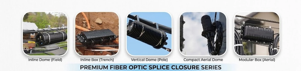
Troubleshooting Link Degradation
-
Localized Signal Loss: Inspect connectors and splices for contamination, microbending, or fracture. Inspect fiber routing inside trays to confirm fiber loops maintain a bend diameter >= 35 mm. Re-splice damaged joints and replace defective protective sleeves.
-
Moisture Ingress: Check the housing perimeter and cable entry seals for leaks. Dry internal moisture thoroughly. Clean any accumulated residues, inspect optical fibers for water-induced surface micro-cracks, replace degraded sealing kits, and re-seal the housing.
-
Cable Strain Damage: Verify that cable clamps firmly grip the sheath and that strength member lugs remain tight. Adjust clamping hardware to eliminate external pulling forces transferring to splice trays.
Maintaining detailed maintenance logs—recording splice tray allocation, re-entry dates, technician identity, and optical time-domain reflectometer (OTDR) trace references—ensures clear traceability across the network lifecycle. A well-constructed fiber optic splice closure remains the primary defensive barrier protecting network reliability across the outside plant.